Wiring the LCD display with the microcontroller and the power module Circuit Diagram The problem is that if it was done the same way we turn an LED on, then for a small 320x240 screen we need 76800 microcontroller pins. It seems that the procedures should be different somehow. Now, to make the design practical, the task of driving LCD pixels using microcontroller is divided in to two steps. For the first step, there is a 16×2 LCD. We always use devices made up of Liquid Crystal Displays (LCDs) like computers, digital watches, and also DVD and CD players. They have become very common and have taken a giant leap in the screen industry by clearly replacing the use of Cathode Ray Tubes (CRT). CRT draws more power than LCD and is also bigger and heavier. An LCD is a display screen widely used in embedded systems and microcontroller-based projects, capable of displaying alphanumeric characters and even basic graphics. The most common type of LCD used with Arduino is the 16×2 LCD, where "16×2" means it can display 16 characters per row across two rows.

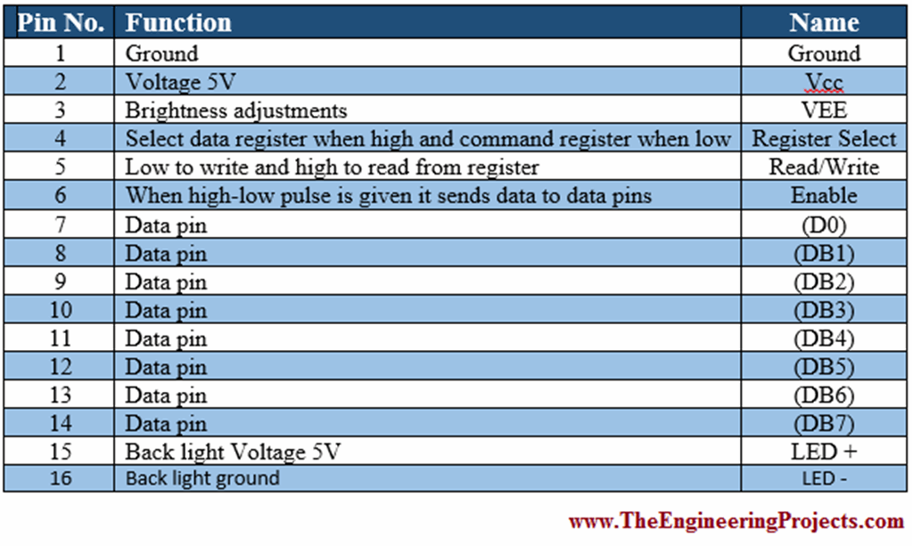
can be used to interface with an LCD screen. Method Interfacing an Arduino microcontroller with an LCD display consists of two parts, wiring and programming. Wiring A typical LCD display consists of 16 pins that control various features of the screen. A table that shows the pins and describes each function can be seen in Table 1 below. The

How to interface a LCD screen with a microcontroller : r/embedded Circuit Diagram
Depends on the LCD you're using and which microcontroller you are using. However, regardless of lcd, the interfacing is somewhat same. I recently had the experience of interfacing OLED with Zedboard and here are the steps I followed: identify the communication protocol (for me it's was SPI) Send the initializing sequence using a state machine

Now connecting TFT LCD and some LED to ESP32.as picture above, since ILI9341 using logic 3.3 V u can directly connect to ESP32 if u are using microcontroller that are use 5V connect VCC and LED to 3.3V. here the list of connection : CS - D15 ; RESET - D4 ; DC - D2 ; MOSI - D23 ; SCK - D16 ; LED - 3.3V ; MISO - D19
PDF Interfacing to an LCD Screen Using an Arduino Circuit Diagram
Before wiring the LCD screen to your Arduino board we suggest to solder a pin header strip to the 14 (or 16) pin count connector of the LCD screen, as you can see in the image further up. To wire your LCD screen to your board, connect the following pins: LCD RS pin to digital pin 12; LCD Enable pin to digital pin 11; LCD D4 pin to digital pin 5

The 16×2 LCD pinout is shown below. Pin1 (VSS/Ground): This is a GND pin of display, used to connect the GND terminal of the microcontroller unit or power source. Pin2 (VCC/VDD/Source Pin): This is the voltage supply pin of the display, used to connect the supply pin of the power source. Pin3 (V0/VEE/Control Pin): This pin regulates the difference of the display, used to connect a changeable When using PIC microcontroller, the mikroC compiler has a built-in LCD library that supports the commands to carry out LCD initialization. The library consists of a number of functions to control LCDs with 4-bit data interface. The main program first clears the LCD screen and then displays "LCD INTERFACE" in the first row of LCD. PIC microcontroller LCD interfacing MPLAB XC8 MikroC LCD Library Code Example. 2 Sending Data To The LCD. We'll be using the 4-Bit interface in these tutorials as it's the most common and most wished for. until I realized that you did not have any delay after the function commands for things like clear screen and moving the cursor