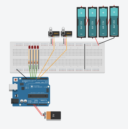
Voice Control Home Automation Circuit Diagram To build a smart home automation system using Arduino, you will need the following components: - Arduino UNO - Relay module - HC 05 Wireless Bluetooth Module - Lamp - 2.2k ohm resistor
Home automation is rapidly becoming a part of modern life, allowing us to control household appliances with minimal effort. One of the most exciting advancements in this field is voice control, where you can manage your devices using simple voice commands. In this article, we'll walk through how to design and simulate a voice-controlled home automation system using TinkerCAD, leveraging the On the other hand, voice recognition wireless home automation as created an avenue for real life voice command interaction between the consumer electronics [home appliance] and the consumers/users Before this, we have built some IoT Home Automation Projects, here are some examples: IoT Based Manhole Monitoring System; Create an Android App with Android Studio to control an LED over WiFi using NodeMCU; Home Automation with Node-RED and Raspberry Pi: Control Lights & Read DHT11 Data . Components Required. Arduino UNO; HC-05 Bluetooth Module
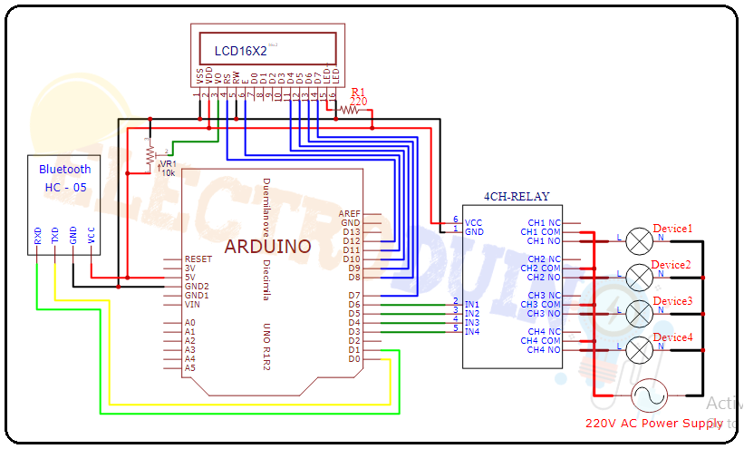
PDF VOICE CONTROL SYSTEM FOR HOME AUTOMATION Circuit Diagram
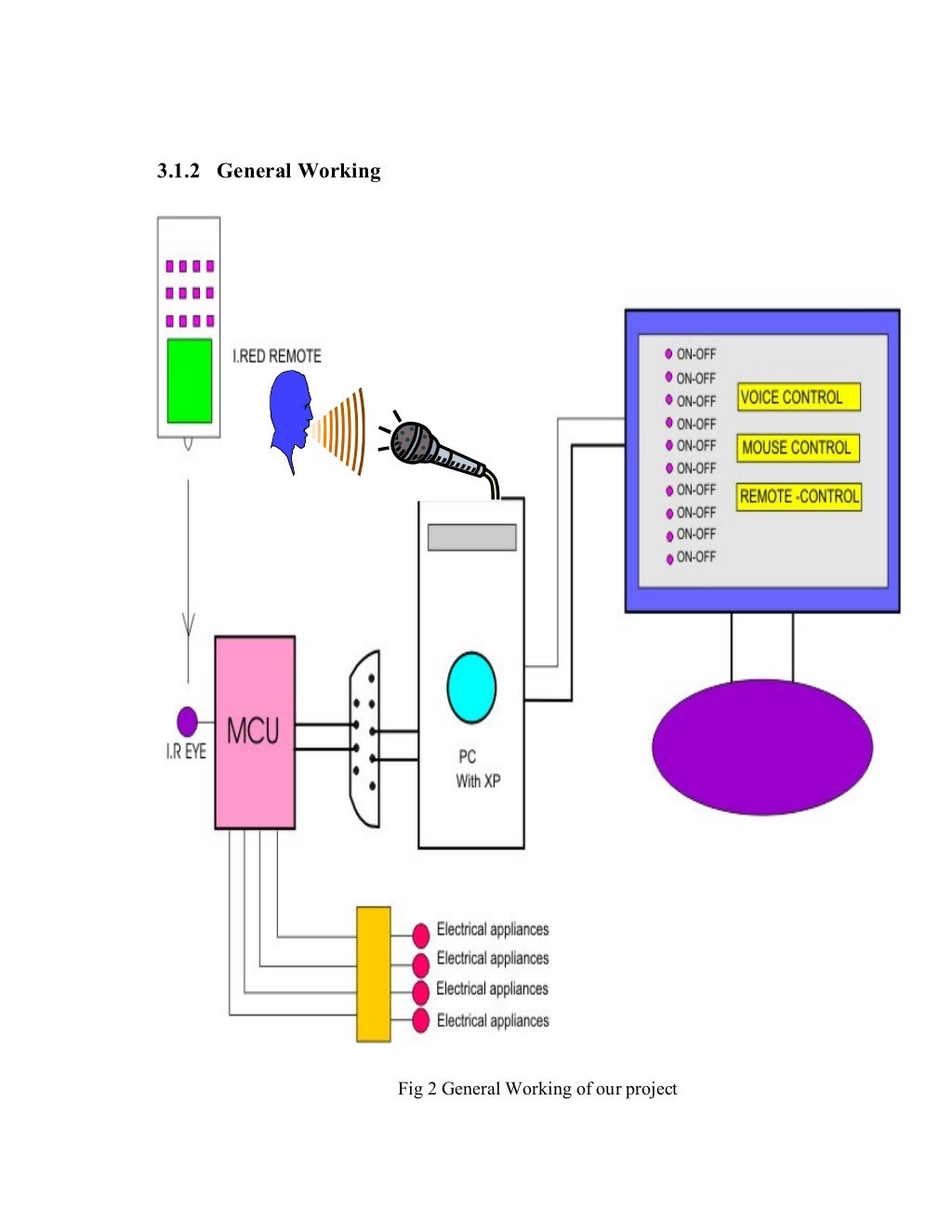
An automated home automation system makes it easy to switch the Appliances just by a click through our mobiles. This system uses wireless technology to control home appliances. The Android app designed by us uses the voice commands to control the home appliances over bluetooth. Figure 1: System Design 3.SYSTEM DESIGN
Home Automation PCB & Gerber File. If you don't want to assemble the circuit on a breadboard and you want PCB for the project, then here is the PCB for you. The PCB Board for the Home Automation Project is designed using EasyEDA online Circuit Schematics & PCB designing tool. The front side and back side of the PCB is given below.
Controlled Home Automation System Using TinkerCAD Circuit Diagram
system for residence automation and security based on speech recognition is shown in Fig. (1). The project encompasses code as well as hardware. As a piece of hardware, it enables voice control of home appliances using voice input commands. The block diagram portrays the following components: Raspberry Pi,