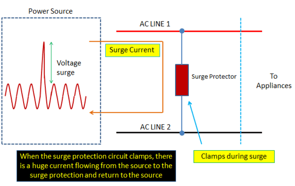
Surge protection circuit and production method thereof Eureka Circuit Diagram Circuit Description of Three-Phase Power Surge Protector Circuit. The circuit diagram of the appliance protector is shown in figure 1, build around timer IC 555, relay, transformer, and a few other passive and active electronic components. This circuit utilizes three transformers and three relays one for each phase. unbalanced operation of surge protection devices on the line. Unbalanced current flow to earth ground through those devices then produces large voltage differences between conductors in the pair. 2 LIGHTNING SURGE AND AC POWER FAULT TESTING The product development schedule must contain ample time for testing. The budget for compliance Table 1: IEC 61000-4-5 Surge test voltage for ac and dc power supplies connected to mains power Surge Suppression Circuits and Devices. Protecting power supplies and their loads from surges typical requires some form of internal or external surge protection circuit. There are two main classes of surge protection circuits: Clamps; Crowbars
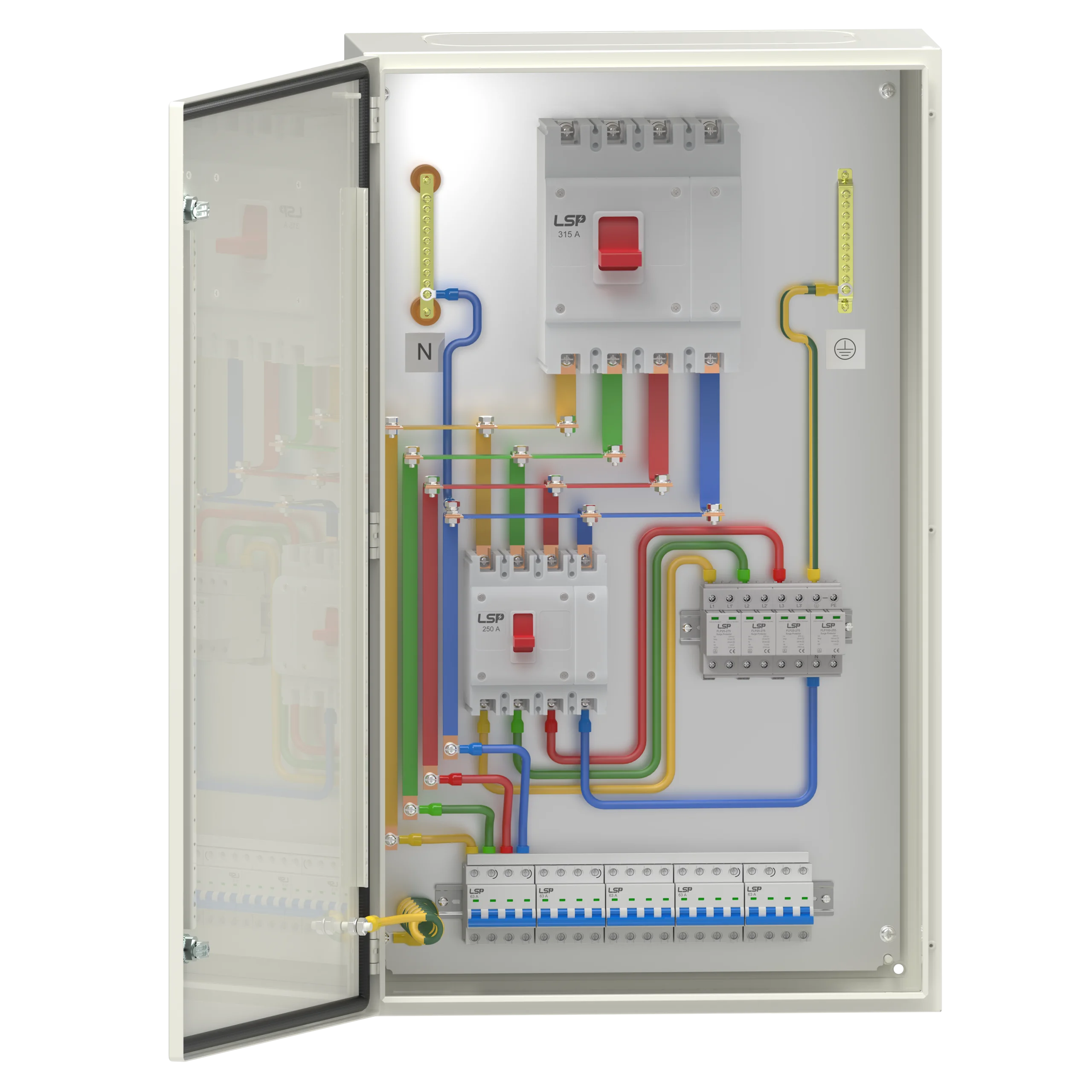
The main part that stands out is the ground or earth connection. The surge protection device is grounded specifically to power earthing in case of high-power loads and instrument earth in case of low-power loads. Surge protection device has a very high impedance. So, it does not pass normal flowing voltage.
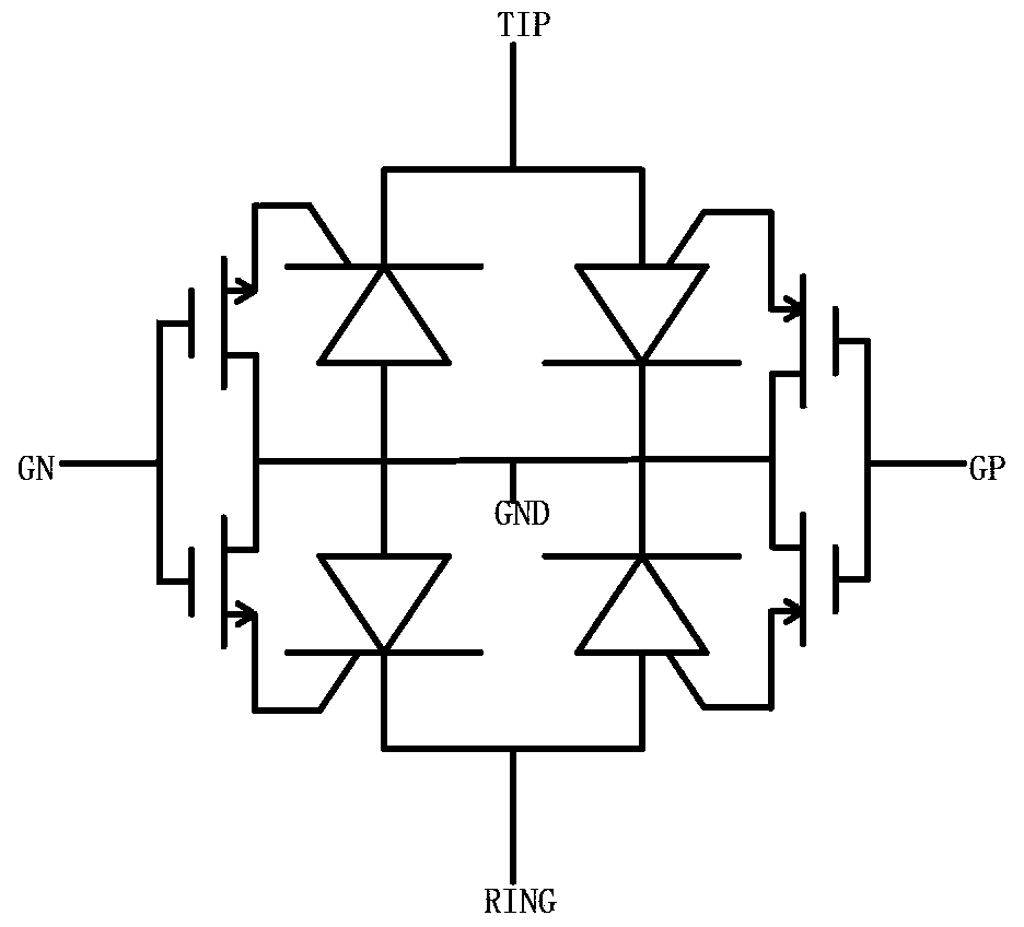
Designing Your PCB for Transient Voltage Suppression Circuit Diagram
On few cases, surge protection circuit is needed across line and ground. This is especially at higher surge voltage requirement (4kV and up). Using MOV as Surge Protection Device Basic Properties. MOV stands for Metal oxide varistor; is commonly used surge protection in power lines; MOV is a voltage dependent resistor
emystiying surge protection ecemer 2018 Surge testing examples Going back to the 1kV voltage transient on the motor, let's look at how that test scenario is defined in IEC 61000-4-5. Figure 5 shows the test setup on the motor drive, with the CWG setup simulating a high-energy surge event that is coupled directly to an equipment cable.
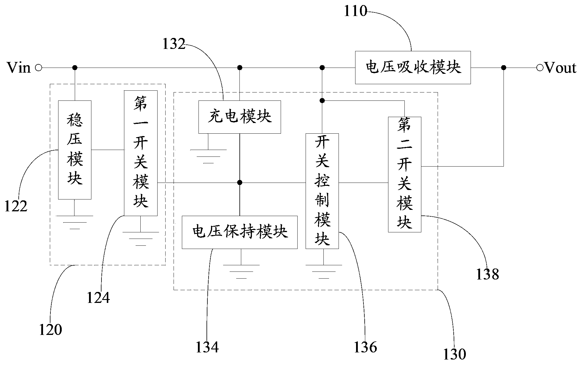
Surge Protector Circuits: Principle, Selection, And Design Circuit Diagram
The crowbar is another type of surge protection circuit that functions differently from clamps. Crowbar devices short circuit the circuit nodes together, bringing the voltage close to zero instead of limiting it to a maximum value. Gas discharge tubes (GDT) are commonly used as crowbars. GDTs, similar to TVSs, behave as voltage-dependent switches.

2. Surge protection: what should be noted? 10 2.1 This is how surge protection works 10 2.2 Lightning and surge protection standards 11 2.3 Basic protective measures and equipment 13 2.4 Lightning protection zones 14 2.5 The protective circle principle 15 3. Classification and testing ofsurge protective devices 16
