Stereo Graphic Equalizer Circuit Diagram Wiring Diagram How to Build Your Own Audio Equalizer. An equalizer is a device that allows you to adjust the gains of individual frequencies. You may want to lower bass, so on an equalizer, you would go to the frequency range of bass, which may be around 500Hz and turn down the volume. If you want to increase treble, you may go to, say, 2KHz, and turn the This is 4 volume audio equalizer. It's mono audio. if we want stereo then we have to use 2 circuits. one circuit for the right side and another circuit for the left side. both circuits need 12 voltages. 1st one is volume. 2nd one is high. 3rd one is mid. and 4th one is low. with 4 band circuit. To understand this, in this tutorial, we are going to make an "Audio Equalizer Circuit". The circuit uses the IC LA3600. The LA3600 is a single integrated Op-amp with a single operational amplifier and a graphic equalizer with five bands for one channel. By connecting two LA3600, we can make ten equalizers, each of which can regulate

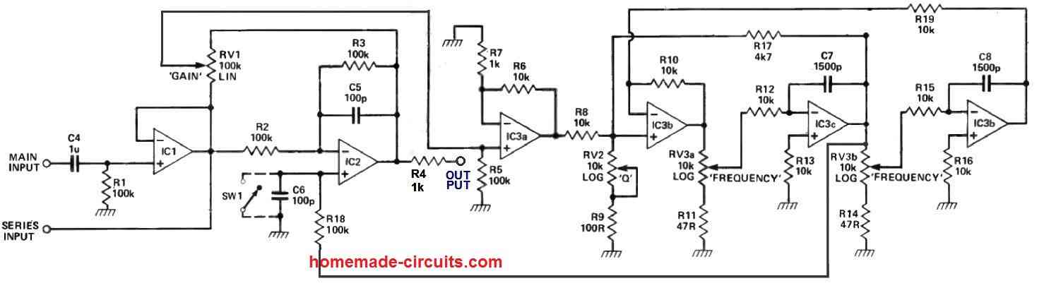
This 3 band equalizer circuit is an active filter network for bass, mid and high audio ranges. It is designed around the LM833 opamp from National Semiconductors. This opamp IC has the following charactersistics: very low noise figure, wide bandwidth and a relatively high slew rate. How does the three band audio equalizer works Active Audio Filter PCB Design. The PCB for our Active Audio Filter circuit is designed for a double sideboard. I have used Eagle to design my PCB but you can use any Design software of your choice. The 2D image of my board design is shown below. Sufficient ground filling vias are used to properly create the ground path all over the circuit board.
Building a Three Channel EQ on a Breadboard Circuit Diagram
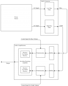
The equalizer consists out of an audio input. This input signal is filtered by a active notch filter - active, because i need a high filter order - and the lasting signal is amplified. This also keeps the circuit small.!! Important remark: !! Make sure, your 5V reference supply can act as a sink, since its not in source configuration. That In the previous tutorial, an audio crossover was designed using high pass and low pass audio filter. In this tutorial, an audio equalizer will be designed. An Equalizer (abbreviated as EQ) is an audio equipment which cut or boosts the certain frequency components from the audio signal. This process of adjusting the frequency components is called as Equalization.The equalizers are widely used In this audio equalizer, we use the LF351* op amp. It is an integrated circuit and it uses an 8-pin dual in-line package, which can easily plug into the breadboard. There is no specific ground connection. For our circuit, use op amp power supply voltages of 12V for the positive terminal (pin 7), and ground the negative power terminal (pin 4).
Testing and Troubleshooting an Audio Equalizer Circuit. In order to ensure that an audio equalizer circuit is functioning properly, it is important to test and troubleshoot the circuit. This will help identify any issues or problems that may be affecting its performance. Here are some steps to test and troubleshoot an audio equalizer circuit: 1. Once the circuit is assembled connect an audio source e.g. a music player to the input of the equalizer. Connect an amplifier or headphones to the output of the equalizer. Power on the circuit and test the equalizer by adjusting the potentiometers for each band to see the effect on the audio output. Adjustments