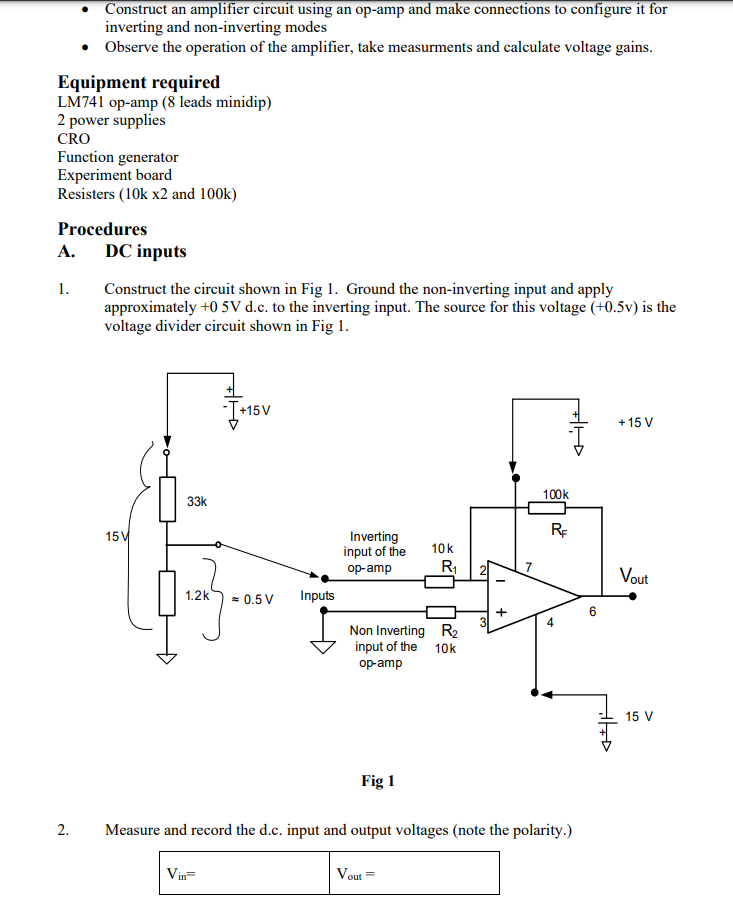
Solved DESIGNING AMPLIFIER CIRCUIT USING OPAMP design an Circuit Diagram 1.1 Simple op amps Objective. In this lab we introduce the operational amplifier (op amp), an active circuit that is designed with certain characteristics (high input resistance, low output resistance, and a large differential gain) that make it a nearly ideal amplifier and useful building block in many circuit applications. The identical 741 op-amp can also be used in a circuit which does not depend on an external signal source (AC mains hum). The 741 op-amp is used in a high-frequency oscillator circuit that operates around its peak frequency in this very unique proximity sensor device described below. The internal feedback capacitor of the 741 op-amp restricts This project is a brief introduction to build a simple signal processing circuit. It uses two LM741 Operational Amplifier ICs (opamp). It will accept a signal from the function generator and will couple it via a first op amp in a buffer or impedance coupler configuration. Then the resulting signal is fed into an inverting amplifier.

Only a couple resistors and capacitors are needed to make a simple audio amplifier. The chip has functions for gain control and bass boost, and it can also be turned into an oscillator capable of outputting sine waves or square waves. The LM386 is a type of operational amplifier (Op-Amp). Operational amplifiers have a basic task.

StudentZone activity: Simple op amps & amplifier configurations Circuit Diagram
The opamp circuit using transistors appears reasonably linear (reduced distortion) as pointed out in the scope picture listed below. The upper waveform is the ramp input from a function generator, and the bottom waveform is the inverted output of the op-amp having a 50 ohm load.

A simple voltage follower. The input can vary from -12 to +12, starting at +2.5 V and seeing how far positive and negative the op amp will recognize. The LM741 would not recognize an input voltage lower than 1.8 V or higher than 4.4 V. The LM741 is used in many schools because it is a good example of the problems with op amps. Offset voltage: The DC voltage that, when applied between the input pins, will cause a DC output voltage of zero. If both inputs were grounded, the output voltage of the op-amp would not be zero. Slew rate: The time taken for the output to change for a given input.Specified as V/mS. Equivalent input noise voltage: The noise performance of the op-amp. An ideal voltage source is placed in series A Simple Audio Amplifier with LM741 Op-amp is a basic audio amplifier circuit designed to amplify weak audio signals and drive a speaker. The LM741 is used as the primary amplification component, while the other components like the BC547 transistor and capacitors provide further amplification and stability to the circuit.

Simple Audio Amplifier With LM386 : 5 Steps Circuit Diagram
An op-amp has two inputs, an inverting terminal (labeled „-") and a non-inverting terminal (labeled „+"). And has a single output. The first input is called inverting because the output voltage is inverse of the voltage applied at the inverting input, times the gain of the amplifier circuit.If we apply the signal to the non-inverting input we get the same signal on the output, times gain. Designed to amplify a small signal up to something useful, op-amps are applicable in an extremely wide range of projects, everything from audio circuits, to data acquisition, to signal processing. My goal is to simplify the op-amp into something easy and fun to use, highlighting the important stuff and keeping it simple.
