RFID Security System With Arduino Circuit Diagram To make the hardware connection easy to understadn we have given a table below which explains the connection between your Arduino board and the RFID, LCD and Relay modules. Projects Using RFID for Security and Automation. Learn how to build an RFID-Based Door Lock System using Raspberry Pi and an RC522 RFID module for secure access

About the System Design. An RFID based Door Lock is based on some simple concepts. We store a set of RFID card data in our system, say 3 or 10 RFID card data. When the person with the right RFID card (compatible to data preloaded in our program/system) come and swipes his RFID tag, access will be granted.

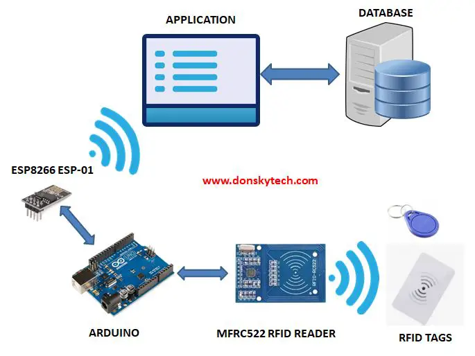
Arduino Based RFID Door Lock Circuit Diagram
By coupling the versatile Arduino microcontroller with the RC5222 RFID module, we can develop a robust and responsive door lock system.When an RFID tag comes in proximity to the reader, the Arduino evaluates the tag's information against the stored data to ascertain if access should be permitted or restricted. This project provides a practical insight into the workings of RFID technology
To make this circuit easier i will break down the entire circuit into 3 different parts. RFID, Servo motor and LED connections, all the components were connected using jumper wires and for the power supply ill use the USB power via powerbank.

How to make an RFID Door Lock System using Arduino? Circuit Diagram
Learn how to make Arduino RFID/NFC Door Lock system, how to use RFID/NFC tag to unlock the door, how to make a security door lock system, how to program Arduino step by step. The detailed instruction, code, wiring diagram, video tutorial, line-by-line code explanation are provided to help you quickly get started with Arduino. Find this and other Arduino tutorials on ArduinoGetStarted.com.
