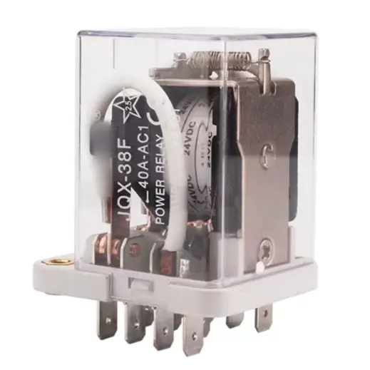
Relay Switch Everything You Should Know Circuit Diagram A relay is an electric switch that uses an electromagnet, when energized, to mechanically open or close contacts that powers an electrical circuit. Solid-State relays (SSRs) is an electronic relay without physical contacts, unlike the traditional type of mechanical relays, it makes use of semiconductor components to provide the switching Applications of Relay. There are limitless applications of relay, its main function is to control the high voltage circuit (230V AC circuit) with the low voltage(DC voltage) power supply. Relays are used in computer circuits in order to perform the mathematical and arithmetic operations in it. It used to control the electric motor switches.

Relays are often used to control circuits through a low-power signal. A relay may also be installed where several circuits must be controlled by one signal. Relays that handle high power may need to maintain an electric motor or other high-power loads to prevent injury and protect from faults and overloads. These types of relays are often Electrical Relays can also be divided into mechanical action relays called "Electromechanical Relays" and those which use semiconductor transistors, thyristors, triacs, etc, as their switching device called "Solid State Relays" or SSR's.. The Electromechanical Relay. The term Relay generally refers to a device that provides an electrical connection between two or more points in A relay is an electromagnetic switch that opens and closes circuits electromechanically or electronically. A relatively small electric current that can turn on or off a much larger electric current operates a relay. Relays work like some electrical products since they receive an electrical signal and send the signal to other equipment by turning the switch on and off.

Electrical Relay and Solid State Relays for Switching Circuit Diagram
That is with relays alone, but with a relay driver, a signal can be changed to switch a relay that needs 100ma (still not recommended from the 555), to switch on 1uA (micro amp). Transistors also come in many different shapes and sizes, and s a result, the pin assignment, for pin 1, 2 and 3, will most often be different. Introduction To Relay and Different Types of Relays | Its Terminals, Working and Applications Relays are the essential component for protection and switching of a number of the control circuits and other electrical components. All the Relays react to voltage or current with the end goal that they open or close the contacts or circuits. This article briefly discusses the relay basics and

The switches are older and have less current carrying capability. Different types of Switches are available based on electronic project requirements. Some of them are toggle switch, slide switch, push-button switch, Rocker switch etc. Here are some of the circuit symbols for relays and switches that are commonly used in electronic circuits As we have seen that relay is a switch. The terminology "Poles and throws" is also applicable for relay. Depending on the number of contacts and number of circuits it switches relays can be classified. Before we know about this classification of contacts we have to know the poles and throws of a relay switch. Poles and Throws. Relays can Relays serve as electrically controlled switches, broadly categorized into electromechanical relays (EMRs) and solid-state relays (SSRs). EMRs utilize mechanical movement to open or close contacts, while SSRs employ semiconductor devices for switching actions.
