Reactive LED Circuit 10 Steps Circuit Diagram How to Make Music Reactive LED Strip / Very Easy👉PCB Drawing ProgramGet a free trial of Altium Designer :👉http://www.altium.com/yt/ZAFERYILDIZ👉Subscribe t In this clip, I used a single color LED strip, but you you can use a single LED, multiple LEDs wired together, single color or RGB LED strip, it just depends on what you are trying to build. The set up is fairly simple, the component list is fairly basic so if you are a tinkerer you should already have the majority of the materials laying around.
In my setup I used two 5m LED strips from Amazon. Each of these strips requires a 2A supply and because I had ordered separately I got two 2A supplies. However you can just use a single 4A supply to power your circuit and your strips. Since I have the circuit with two supplies I will list components according to that. 1> 2 x 5m Led Strips amazon In this video, We'll teach you making a simple sound activated LED light circuit, that circuit led light with dance with the music. You can use this sound re

Reactive LED Circuit : 10 Steps Circuit Diagram
Interesting? So, let us make the Simple Sound Reactive LEDs Circuit. A music-reactive LED circuit is a basic electrical circuit that responds to altering sound levels, generally from nearby playing music, and reflects the change level of intensity of the sound signal as blinking LEDs. Hardware Components. The following components are required 💡 DIY Sound Reactive LED - Build a Voice-Controlled Light Show! 💡Have you ever wanted to create a sound-activated LED circuit that reacts to your voice or Create an immersive audiovisual experience with our DIY Music Reactive LED system, synchronizing aptivating light displays with the rhythm of your favorite music using Arduino. // Analog pin connected to the sound sensor 2 const int ledPins [] =

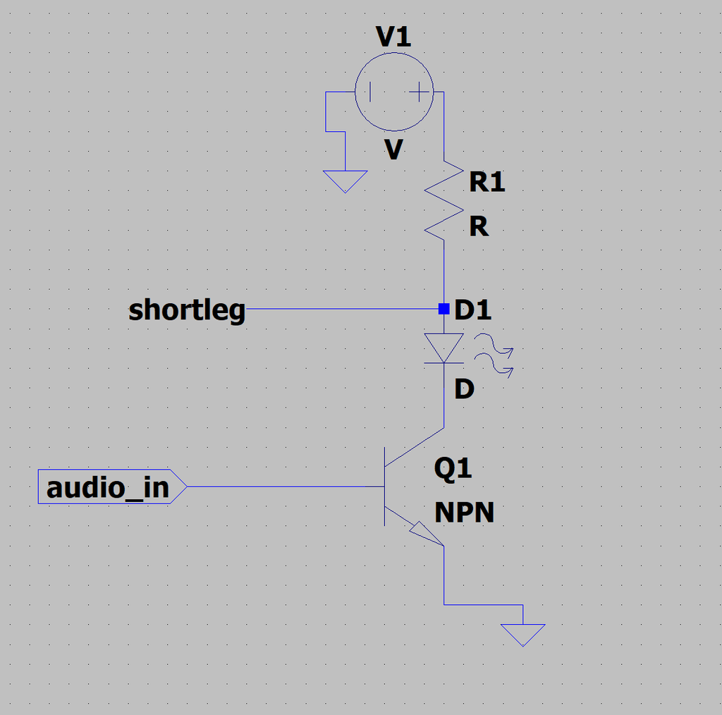
resistance(R) = (power supply voltage - LED voltage drop) / LED current The typical recommended LED current is 20mA, our power supply voltage is 9V, and the LED voltage drop for a clear blue LED is 3.0V. This results in: (9-3)/0.020=300 ohm Of course this doesn't need to be exact, a 330 ohm resistor will work fine here. Step 4: Arduino and Pulse-Wave Modulation. An Arduino Uno is perfect for this project because it can handle the load of the LED strip, you can write multiple programs depending on what particular behavior you would like to see from your LEDs and besides the standard General Purpose Input/Output (GPIO) pins, it also has Pulse-Width Modulation (PWM) pins. A music-reactive LED circuit is a simple electronic circuit that responds to varying sound levels, usually, of the rhythmic melody from nearby playing music, and displays the changing intensity level of the sound signal in the form of blinking LEDs. and displays the changing intensity level of the sound signal in the form of blinking LEDs
