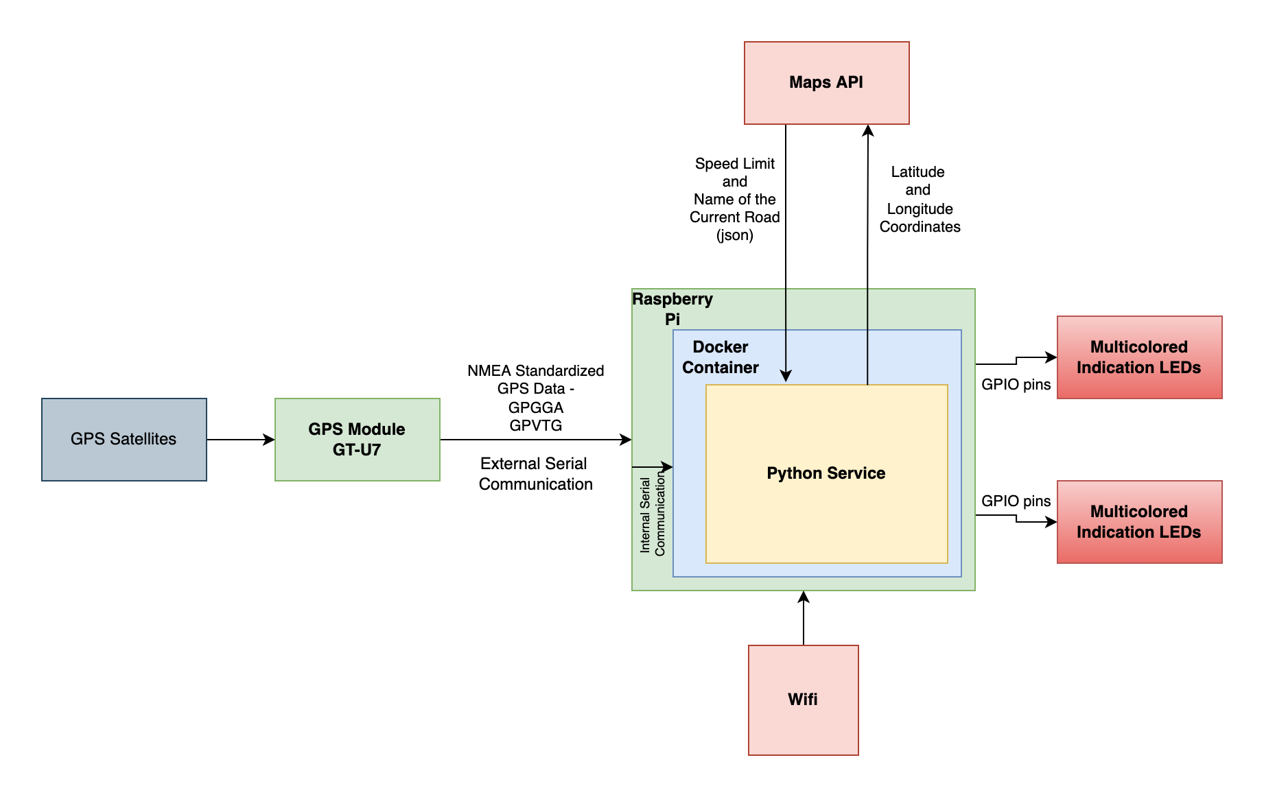
Project uses raspberry pi and gps module Circuit Diagram microcontroller processes this frame and imposes the speed limit on automobile. In order to implement this design in full fledge a separate microcontroller is very essential to handle the tasks like displaying maximum (MAX) speed allowed and other necessary information on Liquid Crystal Display (LCD), If the system was at lower speed than the limit received from the sign post than there will be no changes made to the speed of the system. However, if the speed of the vehicle was manually incremented to a higher value, then the controller will impose the speed restriction and bring back the speed value to the value specified by the limit.
speed, if the driver doesn't respond to it. The microcontroller is used to control the speed of the vehicle according to zones [3]. Embedded Based Vehicle Speed Control System Using Wireless Technology proposed a system that has an alerting, recording, and reporting feature for over-speed violation management. the calculated speed is compared with the limit ed speed. When the calcu lated speed is greater than limited speed, it alarms on, LED 3 blinks and LCD displays the vehicle' s spee d. The co nstructed model of the microcontroller based automobile speed limi ting device a nd a larm control system is presented in Figure 9. Figure 9 shows the various external features of the
PDF Smart Zone Based Speed Control System for Vehicles Circuit Diagram
The STM32 is a powerful 32-bit Cortex-M microcontroller that is extremely common in embedded applications. In fact, it's one of my favorite microcontrollers, especially for non-wireless commercial product applications. They come in a wide variety of flavors from simple versions with only a few pins all the way up to advanced high-performance versions capable of complex tasks like machine show the simulation results for the case where the car speed is less than the set speed limit and another where the car speed is greater than the set speed limit, respectively. Table 1 shows the three possible conditions of the set speed switches and the outputs of the microcontroller. Upon successful completion of the software simulation, xiv This thesis presents design and implementation of the vehicle speed sensor using MAW sensor in a vehicle, circuits for signal processing and speed governor control unit. A microcontroller based algorithm for the speed governor based on PWM duty cycle was also developed and experiments conducted through simulation and actual experiments.