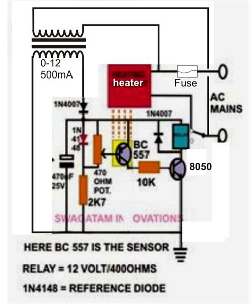
Project Circuit Design Temperature Controller Circuit Circuit Diagram Here is a simple thermostat circuit that can be used to control a relay and supply power to a small space heater through the relay contacts. The relay contacts should be rated above the current requirements for the heater. The hysteresis range (temperature range where the relay engages and disengages) can be adjusted with the 10K resistor Building your own temperature controlled relay circuit. Just follow the steps below and you are ready to get yourself one Temperature-Controlled Automatic Fan! Parts and tools. Arduino UNO; LM35 Temperature Sensor(Celsius) - datasheet; Relay Module ( May refer to my previous post on how to make a relay module) The diy temperature controller circuit described in this article is pretty simple in design and you will love building it. These are more suitable in areas where a precise temperature control may be required. The sensor of the present circuit can be integrated to the heat sink and the relay contacts may be wired either to a cooling fan

This temperature controlled relay circuit is a simple yet highly accurate thermal control circuit which can be used in applications where automatic temperature control is needed. The circuit switches a miniature relay ON or OFF according to the temperature detected by the single chip temperature sensor LM35DZ. When the LM35DZ detects a A temperature controlled relay switch is a useful device that can automatically control the operation of various electronic systems based on the ambient temperature. In this article, we will discuss how to make a temperature-controlled relay switch using the LM358 IC, BC547 transistor, 10k thermistor, 3V & 9V Zener diode, and 10k trimpot. These The relay output of this temperature controlled relay circuit could be attached to either an alarm device, or any kind of heating system, or cooling system. For example the circuit could be used for switching ON a cooling fan as soon as the temperature is detected to be beyond a high threshold.
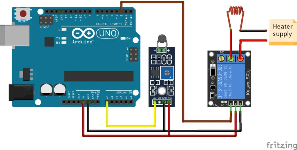
Arduino Temperature Controlled Relay Circuit (DIY) Circuit Diagram
Learn how to use temperature sensor to control relay using Arduino. The detail instruction, code, wiring diagram, video tutorial, line-by-line code explanation are provided to help you quickly get started with Arduino. Find this and other Arduino tutorials on ArduinoGetStarted.com.
1. When the program starts, the relay is initially off (`LOW`). 2. Pressing the button triggers the following sequence: - The button state is read and debounced. - Once the button press is validated, the relay toggles its state (`ON` → `OFF` or `OFF` → `ON`). 3. The relay state is logged to the serial monitor for debugging purposes.

How to build Electronic Thermostat and Relay Circuit Circuit Diagram
In summary, the temperature controller circuit diagram with relay uses a microcontroller, temperature sensor, relay, and LCD display to control the temperature of a system. The microcontroller reads the temperature sensor's data and activates the relay to turn the heating or cooling system on or off based on the desired setpoint. Establishing the circuit design involves developing an accurate schematic that connects all its components. Circuit Diagram Overview: Begin with an orderly diagram that clearly depicts all connections. Connecting Temperature Sensor: Connect it directly to one of your microcontroller's input pins. Temperature Sensor Configuration: