Make Your Own Desktop Self Circuit Diagram 5)The IMU mpu6050 is not perfectly position, when start the robot, observe and adjust so that when the robot in straight up balance position neither motor turns or only turn slightly. To adjust: physically tilt the IMU mpu6050 until reach the desire position, fit with tape or glue gun or other mean to fix the IMU mpu6050. After being inspired by RYNO motors and other self balancing scooters from Segway, I always wanted to build something my own Arduino Segway Robot.Thinking for while, I decided to build a Self Balancing Robot using Arduino.This way I would be able to grasp the underlying concept behind all these scooters and also learn how PID algorithm works.. Once I started building, I realized that this bot Self Balancing Robot is a two-wheeler automated robot that can balance itself from falling to the ground. This is similar to other typical two-wheeled self balancing robots, such as the Segway. Its function is to maintain balance using the motor's axis movement of the wheels and body. Types of self-balancing robots. There are several types of
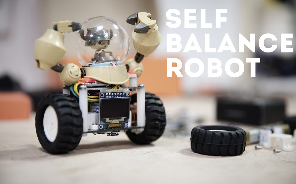
Then below that, I show the code you would need to add to your self-balancing robot code from the previous section in order to make the whole thing work. That's it for now. Hope you enjoyed this tutorial. Keep building! Here is my demo of the robot. Return to Table of Contents. Now we put some value for Kp and perform testing. Too little Kp will make robot fall over. Too much Kp will make the robot go back and forth wildly. A good Kp will make the robot go slightly back and forth. Next we need to set Kd. A gooD Kd value will lessen the oscilation until the robot is almost steady, and will keep the robot standing. As the name suggests, the self-balancing robot is an automated vehicle that balances itself without any outside help or support. This project is a rather complex one as it involves using PID Control and involuted programming. Self-balancing robots are unique among all others, just because of their

BALANCING Robot Circuit Diagram
Make Kp, Ki, and Kd equal to zero. Adjust Kp. Too little Kp will make the robot fall over, because there's not enough correction. Too much Kp will make the robot go back and forth wildly. A good enough Kp will make the robot go slightly back and forth (or oscillate a little). Once the Kp is set, adjust Kd.
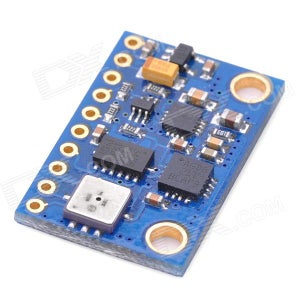
For our self-balancing robot, the angular velocity along the x-axis alone is sufficient to measure the rate of fall of the robot. In the code given below, we read the gyro value about the x-axis, convert it to degrees per second and then multiply it with the loop time to obtain the change in angle. We add this to the previous angle to obtain This is a relatively simple, visually effective balancing robot project that only requires four components to make. Detailed video, instructions, schematic, and code at: Arduino two weel self Balancing Robot Self-balancing robots use a "closed-loop feedback control" system; this means that real-time data from motion sensors are used to control the motors and quickly compensate for any tilting motion in order to keep the robot upright. Similar self-balancing feedback control systems can be seen in many other applications. (AUTOMATIC); pid
