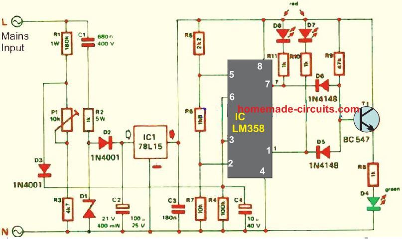
Make an LED AC Voltage Indicator Monitor Circuit Circuit Diagram We have many ways to indicates an AC line. A good way, the AC mains voltage indicator circuit with a LED. It may be the best choice. It save and to be easy.
This LED DC voltage indicator circuit is a voltmeter, rather than simply a battery tester. As such it may measure voltages as low as 3V. It utilizes venerable LM741 operational amplifiers applied as comparators that drive LED indicators. Voltage thresholds are 3, 6, 9 and 12V. Above each incremental threshold an additional LED turns on. In this circuit, we will show how to build a voltage level indicator with a single zener diode. A voltage level indicator is a circuit which can show if the voltage input into a circuit is greater than a certain threshold level. If the voltage is greater than a certain level, then an output such as an LED can light up or a buzzer can sound off.

Electrical Engineering Stack Exchange Circuit Diagram
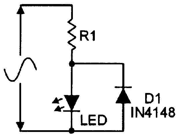
I want to design a circuit that has 3 LEDs connected to it. When the voltage of the power source connected to the circuit is 3.6 volts I want only the first LED to light. 7.2 volts I want the A simple electronic part such as an LED can play an important role in displaying and monitoring the condition of this AC mains voltage and warn us of a possible electrical hazard. Here, I have explained exactly how to make ac voltage indicator using leds through a construction of a little electronic circuit. A voltage sensor circuit is a circuit that can sense the voltage input into it. If the voltage reaches a certain threshold, then an indicator, such as an LED, will turn on.

These are 8 Low Battery Voltage Alarm indicator circuits, as ideas to make small projects, they use LED display easy, cheap with normal parts look below The beeper circuit is built around this IC so when the IC activates it will blink the LED and the buzzer will start producing a beep beep sound, giving an indication of the detection. The time period of LED and buzzer activation is set by the values of the resistor and capacitor used at the input of 555 IC.
How to build 110 and 220V AC LED Voltage Indicator Circuit Diagram
This is four circuits of LED voltage indicator are simple and easy to builds for check voltage battery and others, use as zener,transistor,LM339 and more