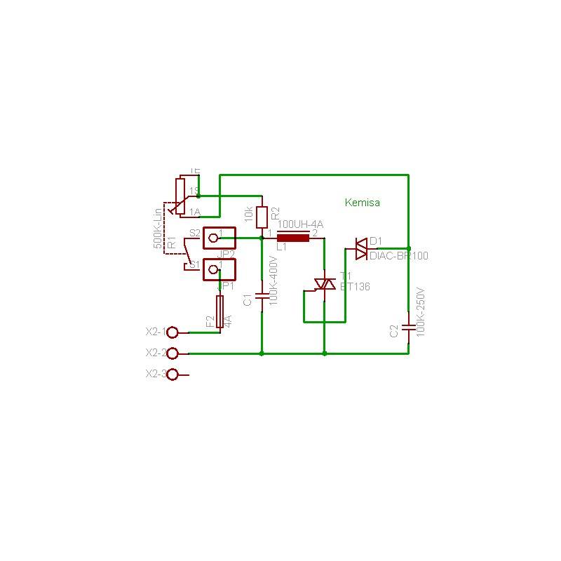
Light dimmer circuit Circuit Diagram To summarize, this will make the lamp glow brighter in the absence of light and in the presence of light the lamp will glow dim or will be turned off. Lets move into the working of this above lamp dimmer circuit. WORKING OF AUTOMATIC LAMP DIMMER CIRCUIT: Triac and LDR holds the significant place in the working of this lamp dimmer.
This automatic light dimmer circuit makes it possible to control a lighting system so that it turns on or off slowly. The circuit works this way: when switch S1 is closed, the capacitor C1 is slowly charged. Once the voltage at C1 reaches 0.6, transistor T1 begins to conduct and the LED also begins to light. If the capacitor voltage increases DPDT Relay Connection Diagram with Dipper Bulb How the LDR Operates. Light falling over the LDR from the headlight of the vehicle coming from the front instantly lowers its resistance and allows more current to flow to the base of the transistor.. The transistor conducts and activates the relay, which in turn flips the contacts such that the host vehicle's headlamps gets connected with the A light-emitting diode (LED) dimmer circuit schematic is a diagram that illustrates the electrical connections and components required to control the brightness of an LED light. LED dimming allows users to adjust the intensity of the light output, providing flexibility and creating a desired ambiance in various applications, such as residential

How To Make A Automatic LED Dimmer Circuit Circuit Diagram
The automatic street light dimmer circuit consist of Arduino which is the brain of the project, an ultrasonic sensor for detecting vehicles or human beings. A 9V regulator is provided for powering the arduino microcontroller board and a MOSFET for driving the LEDs which consumes few amperes at peak brightness. Automatic light dimmers are a great way to save energy and create the perfect atmosphere in your home. And now that you know how they work, you can start creating your own dimmer switches. With a bit of practice and some basic knowledge of electronics, anyone can build a dimmer switch circuit with ease. Working of Light Dimmer Circuit using 555 Timer. The light dimmer circuit discussed here uses a 555 timer IC and MOSFET to control the brightness of an LED strip. The workings of the circuit are as follows: The 555 timer is configured in an astable mode, generating a square wave with adjustable high and low times. The ratio of these high and

Hii Friends, Today i am show you how to make a automatic light dimmer circuit at home. So let's start it. All Component details show in the video. So watch v Light dimmer dims light and glow light with defined manner.Components:1. Arduino Uno/ Nano/ Mega2. Switching Transistor: BC548/BC547/2N2222A or any NPN trans