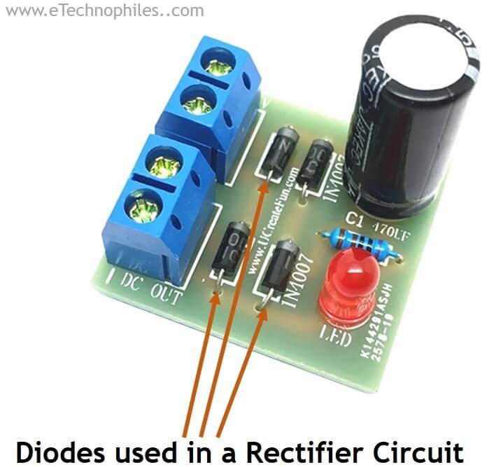
Lecture 3 Diode Rectifier Circuit Diagram How to Make a Rectifier,the concept of the rectifier is not tricky. It is a clever interlock of diodes and electric currents. Here I have explained the basic working principle of rectifier diodes such as a 1N4007 or a 1N5408, and also learn how to connect 1N4007 diodes to build a bridge rectifier circuit quickly. Introduction Diodes are one of the important electronic components used for rectifying an AC into DC. Diodes have the property of allowing DC through a specified direction and rectifying AC across its pin In this lesson, we cover the fundamentals of rectifier diodes, such 1N4007 or 1N5408, and how you can connect them to create a bridge rectifier circuit efficiently. Overview Diodes play a crucial role as electronic parts in converting AC to DC. Diodes can conduct DC in one direction and convert AC to DC across their terminals. Let's delve deeper into the components. Diodes are small electronic

In this tutorial, we're going to learn all about rectifiers and how to build a bridge rectifier circuit out of diodes that can be used in your projects! Learn how a rectifier diode works and how it can be used in power supplies to convert alternating current into direct current. Also get a detailed explanation of the three standard rectifier configurations- half-wave rectifier, full-wave rectifier, and bridge rectifier. Also, find out how to build a bridge rectifier circuit through three simple steps. Full-wave bridge rectifier: Current flow for negative half-cycles. Alternative Full-wave Bridge Rectifier Circuit Diagram Remembering the proper layout of diodes in a full-wave bridge rectifier circuit can often be frustrating to the new student of electronics. I've found that an alternative representation of this circuit is easier both to remember and to comprehend. It's the exact same
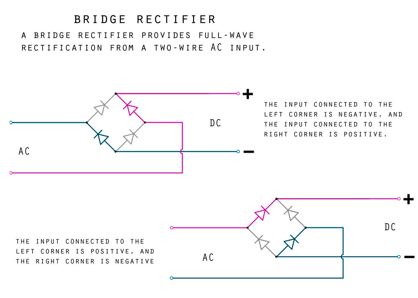
Make a Bridge Rectifier From Diodes : 3 Steps Circuit Diagram
A diode bridge rectifier is a simple circuit to convert from AC to DC using four diodes. Learn how it works with our beginner-friendly guide.

Bits4Bots - Make a Bridge Rectifier From Diodes: In this project we will build a bridge rectifier. In short, take AC and turn it into DC. For most alternative energy applications, we require a direct current (DC) voltage to be generated - for example to charge a bank of batteries. However wind tur…
How to Make a Bridge Rectifier Circuit Circuit Diagram
The rectifier diode lets you convert alternating current (AC) to direct current (DC). In this guide, you are going to learn how this component works and some of the circuits you create by using one. A diode is the most basic semiconductor electronic component, which is built with a single pn semiconductor junction. It has only two terminals, which are referred to as the anode and the cathode. Diodes can be of many different types, such as rectifier diode, zener diode, schottky diode, tunnel diode, varacter diode etc. The most popular among the above types of diodes is the rectifier diode
