Introduction to Capacitive Touch Sensing Circuit Diagram Figure 1-6. 8 mm Touch Sensor By increasing the size of the sensor, the user may place a contact anywhere over the sensor area with no loss in sensitivity. The effective parallel area of the touch contact is limited by the size of the user's fingertip, not the sensor area. Figure 1-7. 12 mm Touch Sensor Hand Shadow exceeds the Touch Threshold, the sensor is In Detect. The sensor is touched by a user touch, or a touch emulator such as a conductive bar, which is connected to earth via a human body model circuit. The threshold is set to a proportion - often 50% - of the maximum touch delta. Figure 1-3. Button Sensor Delta and Threshold Electrode Shapes

To actually perform capacitive touch sensing, we need a circuit that can measure capacitance with enough accuracy to consistently identify the increase in capacitance caused by the presence of the finger. It's important to understand that you cannot simply switch the output state to logic low. An I/O pin configured as an output will drive How to Select the Right Touch Sensing Approach for Your Design. Design tips for using cap sensors. Touche for Arduino: Advanced touch sensing. Tutorial for mimicking Disney's Touché with an Arduino. YouTube: Capacitive sensor, Theory, application and design. Video explanation of cap sensing. MPR121 Hookup Guide. Sparkfun's guide for using a www.ti.com Overview of Capacitive Touch Sensing 2.2.1 Signal As mentioned in Section 2.1.1, the basis of capacitive touch detection is the ability to measure a change in capacitance. This change in capacitance is the signal that the capacitive touch solution identifies. The
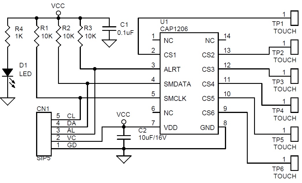
Introduction to Capacitive Touch Sensing Circuit Diagram
At the heart of any capacitive sensing system is a set of conductors that interact with electric fields. The tissue of the human body is filled with conductive electrolytes covered by a layer of skin, a lossy dielectric. It is the conductive property of fingers that makes capacitive touch sensing possible. Table 3-1. Capacitive Touch Versus Capacitive Sensing Requirements. Requirements Capacitive Touch Capacitive Sensing Channel count High (> 8) Low (< 4) Resolution Low High Typical distance 2 to 3 mm Up to 70 cm Sensitivity 10s to 100s fF < 1 fF Requires contact Yes No Power consumption µA to mA range µA range. 4 FDC1004 Theory of Operation Indeed, if you understand the nature of capacitance and the factors that determine the capacitance of a particular capacitor, you are well on your way to understanding capacitive touch sensing. Capacitive touch sensors fall into two general categories: the mutual-capacitance configuration and the self-capacitance configuration. The former, in

Capacitive tactile sensing has been a driving force in the popularization of technologies like capacitive touch screens, enabling intuitive user interfaces in smartphones, tablets, and beyond. For engineers exploring its potential, understanding the core principles of this technology and their applications is essential. Here's a comprehensive look at this fascinating technology and its The first two capacitive proximity sensor circuits uses a simple IC 741 and IC 555 based concepts, while the last one is a bit more accurate and incorporates a precision IC PCF8883 based design.. Working Principle. The following capacitive proximity sensor circuits respond to a human hand by recognizing variations in capacitance when a hand gets closer.
