How to test Potentiometer Circuit Diagram In an actual circuit, it's advisable to include an additional resistor in series to safeguard the LED, even if adjusted to the point where the resistance approaches zero. Potentiometer as Volume Control. In this illustration, all three pins of the potentiometer are employed to establish an uncomplicated method for adjusting the volume of an Potentiometers, or pots, are a type of resistor used to control the output signal on an electronic device, like a guitar, amplifier, or speaker. They have a small shaft on top that functions like a knob; when the user turns the shaft, it turns the resistance on the signal up or down.

A volume potentiometer, also known as a volume control or pot, is a device used to adjust the volume level of audio signals in electronic devices such as amplifiers, radios, and musical instruments. It is essentially a variable resistor that allows the user to adjust the amount of current flowing through the circuit, thereby controlling the volume.

Volume Controller Circuit: Complete Guide on How to Build one Circuit Diagram
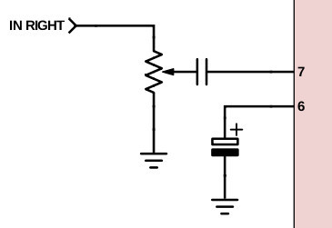
Figure 7: Potentiometer as an electronic control unit. Wiring a Potentiometer is straightforward. First, you'll need to ground the first terminal. Next, you'll need to supply an input signal to the third terminal. Finally, apply an output signal to the center terminal. The following are the critical steps in the wiring process. In a real circuit, Wiring Example #3: Potentiometer as Volume Control. This example uses all three pins of the potentiometer to create a simple way of adjusting the volume of an audio amplifier. By connecting it like this, you'll get a voltage divider that decreases the voltage of the input signal. The more you turn the shaft, the more

Volume Control Circuits. Devices that produce sound through speakers, such as amplifiers in audio systems and televisions, typically use this type of circuit to control the volume of the speakers. Single-Channel Volume Controller . The diagram shows a single-channel volume controller made up of a single potentiometer. It is most effectively used for operations such as volume control in sound systems, display brightness control, and tuning of electronic circuits. The procedure of wiring differs depending on the use of the potentiometer in a circuit. Stepwise Wiring Guide on Using Potentiometer: Identify the Terminals Pin 1 (Fixed Terminal A) → Connected
Potentiometer Wiring Circuit Diagram
We can use this circuit to control the brightness of an LED. Just connect an LED to a resistor of around 350 to 400 ohms, and then connect this to the potentiometer and use a 9 volt battery. It should look like this. When we turn the shaft we can control the current and that changes the brightness of the LED.