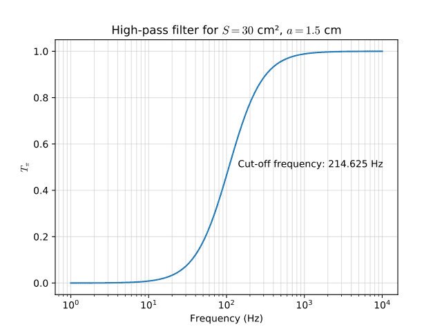
How to make a High Pass Filter YouTube Circuit Diagram Summary: This article shows how to create a simple high-pass filter, starting from a cutoff frequency \(f_c\) and a transition bandwidth \(b\). This article is complemented by a Filter Design tool that allows you to create your own custom versions of the example filter that is shown below, and download the resulting filter coefficients.. In contrast to what you might expect, the procedure to

In this video, we dive deep into the world of **high-pass filters**—what they are, how they work, and how to design them for your projects. Whether you're an
How to Create a Simple High-Pass Filter Circuit Diagram
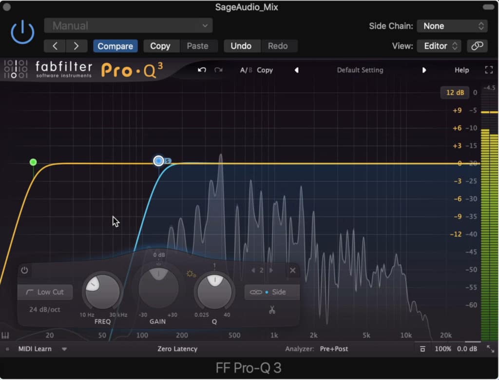
When used like this in audio applications the high pass filter is sometimes called a "low-cut", or "bass cut" filter. The output voltage Vout depends upon the time constant and the frequency of the input signal as seen previously. With an AC sinusoidal signal applied to the circuit it behaves as a simple 1st Order high pass filter. A high-pass filter (HPF) is a circuits that allow high frequency signals to pass through while blocking lower frequencies. Filter Design. That is it, just using simple series capacitors and resistors produces a high-pass or low-pass filter depending on their orientation. Additionally, if you want a slightly different design check out lc
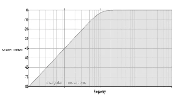
Next, high pass filter is designed to attenuate frequencies from 0 to 9.75 kHz. Cut-off frequency is set to 9.75 kHz and standard capacitor value for audio circuit design chosen to be 0.01 micro Farads. To calculate Resistor values for High pass filter Equation 2 is used. Where: m = magnitude coefficient f c = 9.75 kHz Cs = 0.01 micro Farads D
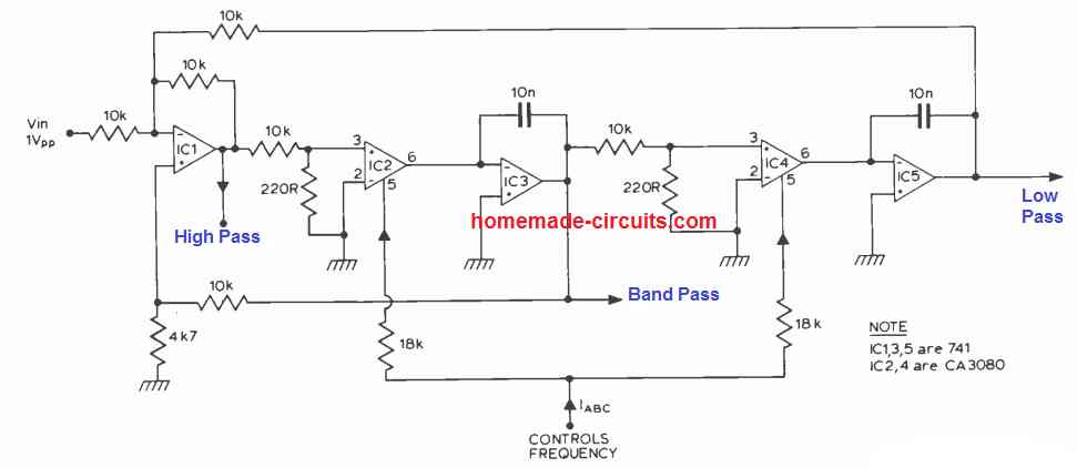
Audio Signal Generators and Filters Circuit Diagram
The most useful filters with ease of use and best all-around performance are the Sallen Key active filters. Sallen Key filters are two-pole filters, meaning they have two reactive components (capacitors). All of the circuits below are based on this design. Low Pass Filter. In a low pass filter, frequencies above a certain point are blocked: How to Design a Customized High Pass Filter. As proposed, to design a high-pass filter circuit quickly, the following formulas and the subsequent steps can be used for calculating the relevant resistors and capacitors. First, select an appropriate value arbitrarily for C1 or C2, both can be identical. Next, calculate R1 by using the following
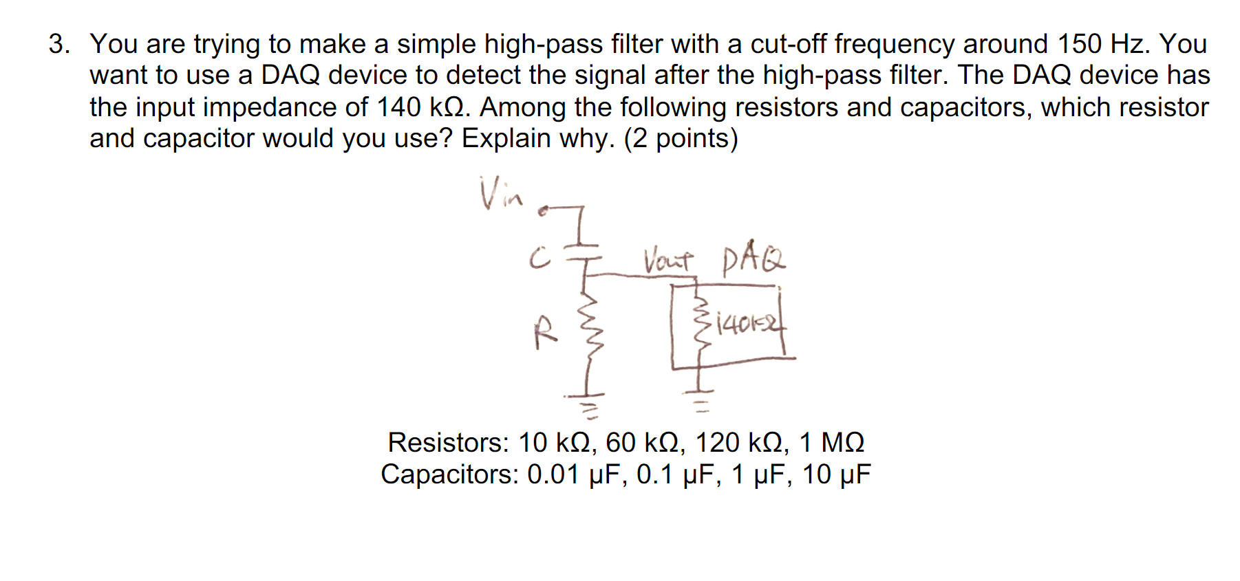
Using the high-pass filter calculator is easy! Here's how: Select the filter type you're designing. The high-pass filter calculator covers the following filter types:. RC high-pass filter;. RL high-pass filter;. Non-inverting op-amp high-pass filter; and. Inverting op-amp high-pass filter.. Input the values for which you are designing. The passive RC and RL filters (both RLC circuits) let you
High Pass Filter Calculator Circuit Diagram
Simple RL and RC circuits serve as high-pass and low-pass audio frequency filters. What it shows: Simple RL and RC circuits act as a passive high-pass and low-pass audio frequency filters. Their effect is clearly evident when listening to music (or white noise). How it works: The high-pass filter consists of a resistor and inductor wired as shown. The reactance of the inductor is low at low
