How to choose a motor driver Circuit Diagram A DC Motor Driver Circuit Schematic is essentially an electronic circuit that is designed to provide power and control signals to a DC motor. This type of circuit typically consists of two parts- the power module, which supplies the energy required to run the motor, and the control module, which gives instructions to the motor such as speed The H-Bridge Motor Driver Circuit . The complete circuit diagram for this H-Bridge using MOSFETs is given below: Working Explanation. 1. The 555 Timer. The timer is a simple 555 circuit that generates a duty cycle from around 10% to 90%. The frequency is set by R1, R2 and C2. High frequencies are preferred to reduce audible whining, but
All of these components come together in a schematic diagram of a typical DC motor driver circuit. This diagram helps provide a clear understanding of the different components and how they interact to ensure smooth operation and optimal performance. By understanding the various pieces of the puzzle, you'll be able to troubleshoot issues and
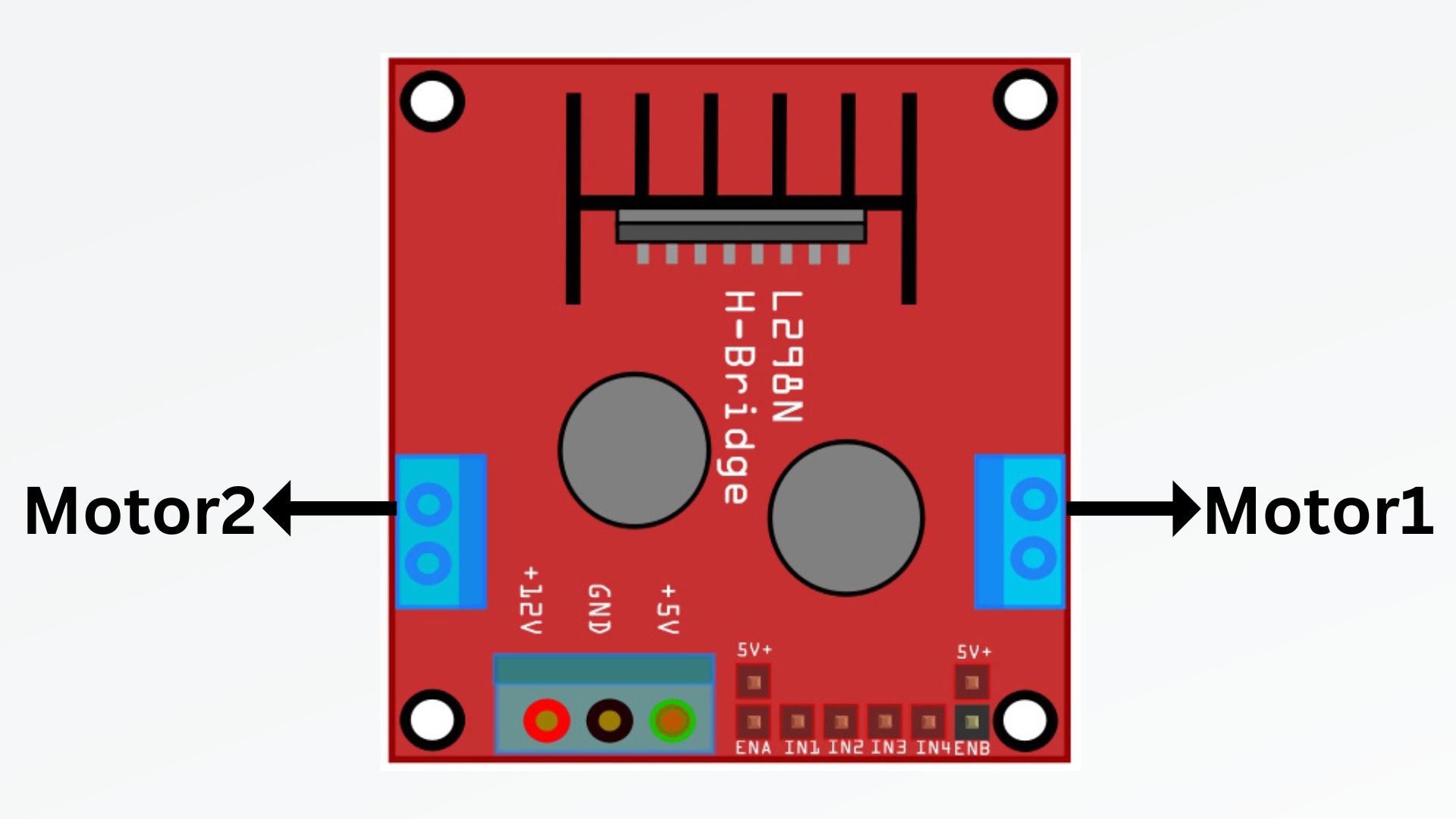
L298N Motor Driver Module Pinout, Datasheet, Features & Specs Circuit Diagram
BTS7960 Circuit Diagram. This is a potential motor drive circuit that may be used in electronic competitions. It includes the PCB and schematic of the BTS7960 dual motor driver board. The circuit uses the BTS7960 as the motor driver chip and incorporates the 74HC244PW for isolation (utilizing the TSSOP package). Key learnings: Stepper Motor Driver Definition: A stepper motor driver is defined as a circuit used to drive or run a stepper motor, consisting of a controller, a driver, and motor connections.; Essential Components: Key components include a microcontroller, a driver IC like the ULN2003, and a regulated power supply.; Stepper Motor Controller: The controller must have at least 4 output pins

Learn how to control DC motors with an L298N motor driver module based on H-bridge configuration. See the pinout, schematic diagram, features and specifications of the L298N IC. Learn how to use L298N Motor Driver Module for driving DC and Stepper Motors. See pinout, datasheet, features, specifications and internal circuit diagram.

Schematic Diagram Of A Typical Dc Motor Driver Circuit Circuit Diagram
The circuit diagram of the L293D Driver Motor IC designed for soldering on PCB with the connectors is shown in the figure below. Here, four inputs such as Input 1, Input 2, Input 3, and Input 4 are given at input pins 2,7,10, and 14 respectively. Two Enables such as Enable 1,2 and Enable 3,4 are given at enabling pins 1 and 9 respectively. It is a popular and applicable MOSFET driver IC. The schematic diagram of the circuit demonstrated in figure-1. Step 4: Figure-2, Designed PCB Layout for the Motor Driver Schematic. I did not have the PCB footprint and schematic symbols of IR2104 [1] and IRFP150 [2] components. Therefore I use the SamacSys provided symbols [3] [4], instead
