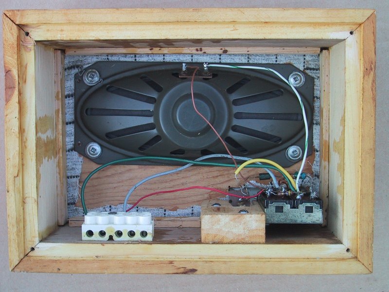
Full Electronics DIY Project Circuit Diagram View the complete project tutorial: https://circuitdigest.com/electronic-circuits/two-way-intercom-circuit-diagramIn this circuit we are going to build a ver

With a typical 9 volt battery, you should get 20-30 hours of use out of the intercom. Keep in mind that the phones still use a small amount of electricity even when they are hung up. So the battery will not last forever. If you would like to make this project a more permanent intercom system, you can replace the battery with an AC power adapter. Home intercom systems can be installed to enable instantaneous communication by linking one room to another. Although intercoms can be purchased commercially, they come with a price. However, you can build your own intercom system for your home for a low cost with existing corded telephones.

How to Make a Homemade Intercom Circuit Diagram
The Basics of Intercom System Schematics. Let's take a closer look at the key components and design considerations involved in intercom system schematics.The intercom circuit we will be discussing is a simple and easy-to-build design utilizing the LM386 audio amplifier. This circuit requires minimal external components, including a condenser microphone, a speaker, and a few resistors and Did you know you can build your own home intercom? Read our instructions and find a circuit of a versatile home intercom system. The unit is able to communicate to as many as ten different locations or rooms discretely and incorporates a single change over switch for the required selections, instead of the age-old keypad system. And all these improvements are set-forth using ordinary low cost Create your own home intercom system using a Raspberry Pi and your mobile devices! From a two bedroom house, to a twenty bedroom mansion in the country, our home intercom system will help you and your family stay connected and best of all it won't cost you a penny in cell phone bills. All you need is a spare Raspberry Pi and an app on your

Make sure the phones work: Temporary replace your home phone with one of the project phones, check to hear a dial tone. Then make a call to see if the microphone and the speaker work in the handset. And to see if the handset has a charge if it applicable. If you fail to make a call for any reason the phone is bad. Make sure the Coupler makes a How it Works. If you are looking for a simple and low cost intercom system for home installation, you would love the explained project. The circuit only uses a single chip for the amplification purpose and a couple of speakers along with a handful of passive components for acquiring the intending intercom application circuit. Welcome to the world of do-it-yourself home intercom systems, where you can enhance your home's communication with easy installation and user-friendly systems. With inexpensive devices or software, you can create a custom intercom system tailored to your needs.Whether you prefer to use smartphones, Bluetooth speakers, voice assistant devices, desktop-based software, or even create a simple