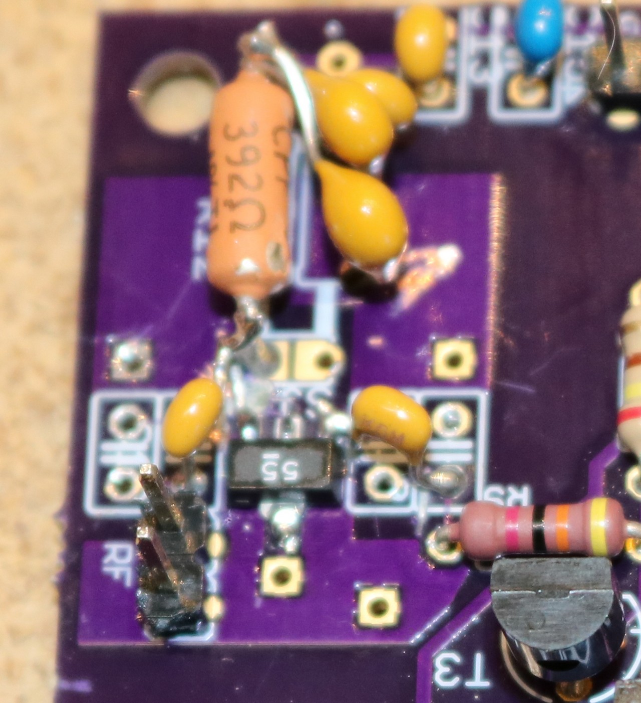
Full Circuit Diagram with Component Layout The circuit that appeared here can be utilized to distinguish a wide band of RF signals and give caution when it will detect an RF signal. However, the circuit can be exceptionally valuable for electronic understudies who make Radiofrequency and FM transmitter circuits. Moreover, the circuit is utilizing just a couple of parts which are two diodes OA91, two transistors, one 10K Very cool RF mobile signal detector from simpletronic - the circuit is main driven by high frequency RF transistor up to 6 Ghz maximum. It can easily detect low frequency and high frequency electromagnetic and RF signal. The detector circuit is responsible for converting the amplified RF signal into an audible or visual signal that can be interpreted by the user. This can be accomplished using a simple diode detector circuit, which rectifies the RF signal and produces a DC voltage proportional to the signal strength.

The diodes may be small signal germanium or silicon although Schottly diodes are preferred. Assemble the components on a small piece of printed circuit board. Use wire probes or a BNC coax socket at the RF input with very short leads to the PCB. To make the RF signal detector circuit, you need to pre-amplify the noise signal which is produced with the help of an LM386 operational amplifier and a BC550 transistor pre-amplifier.
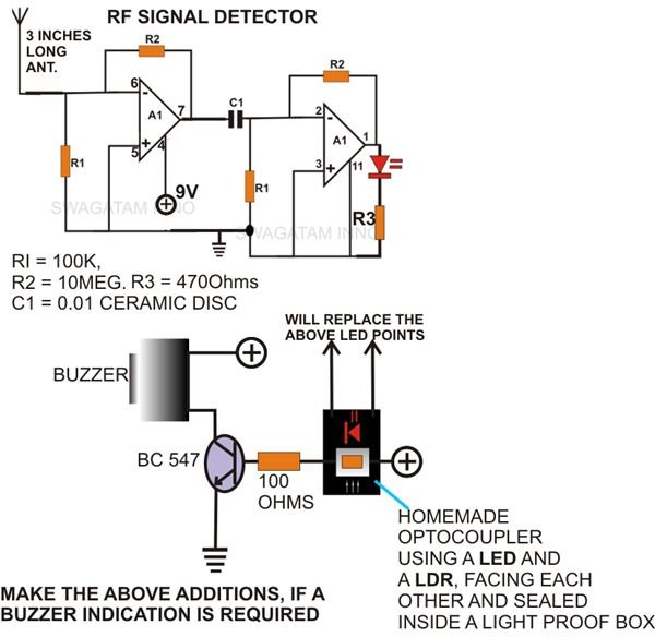
Simple RF Detectors Circuit Diagram
To test the circuit, hold the antenna near an RF source (e.g. a radio or cell phone), and the LED should light up when it detects the signal. It is essential to be cognizant of the safety risks that are associated with RF radiation and take proper measures when constructing or using an RF detector. 3 Simple RF Detector Circuits / Radio Signal Field Detector Get a free trial of Altium Designer : 👉 http://www.altium.com/yt/ZAFERYILDIZmore This simple RF signal detector circuit can be used to trace the presence of RF signals and electromagnetic noise in your residential area, office or shop. It can be a useful tool while testing or designing RF circuits. It can also be used to detect electrical noise in your premises.
A DIY RF detector is an electronic device that detects RF signal waves from a wireless or wired transmission cable. An RF detector is important because it can detect listening devices, bugs, and other surveillance tools in a room. However, it has other uses and levels of advancement. You might have an anti-spy RF detector circuit or a simple low-power radiofrequency technology to spot objects

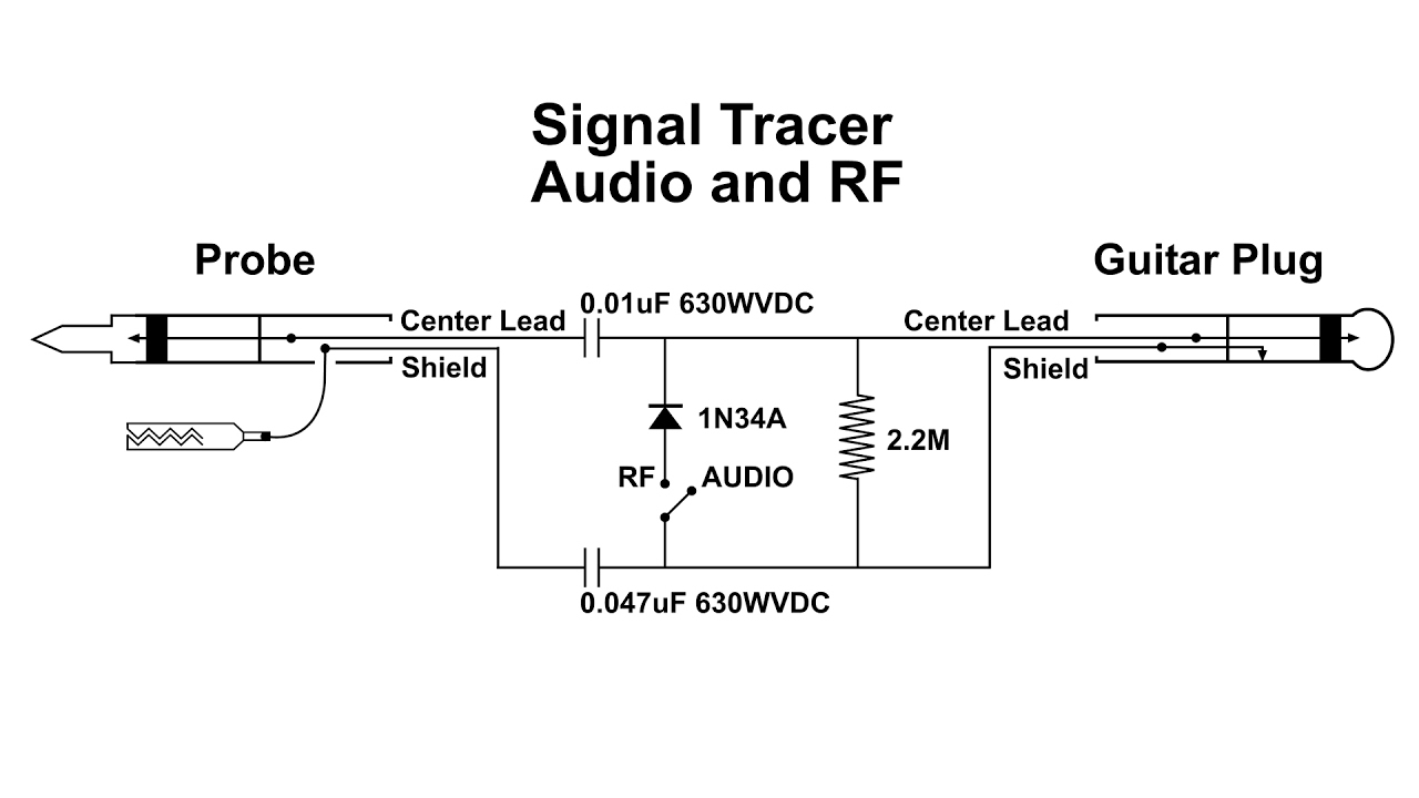
Full Circuit Diagram with Component Layout
However, for this simple transistor RF detector to work a super clean, alcohol-washed veroboard would be required, under reduced humidity circumstances. Temperature variations, light beaming on the transistor, and other inbound signals would almost certainly still trigger the circuit and could make it unstable.