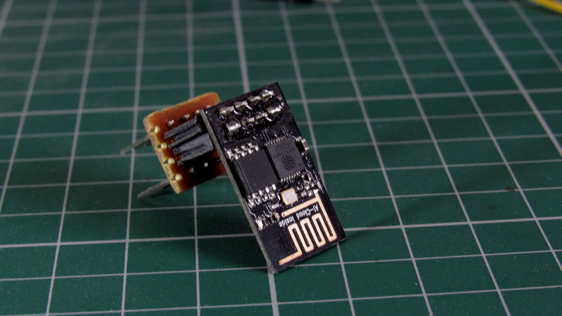
ESP 8266 Wifi Controlled Home Automation 5 Steps with Pictures Circuit Diagram The heart of today's project is the WiFi enabled board that needs no introduction; the ESP8266 based NodeMCU development board. It is an open source platform for developing WiFi based embedded systems and it is based on the popular ESP8266 WiFi Module, running the Lua based NodeMCU firmware.NodeMCU was born out of the desire to overcome the limitations associated with the first versions of
Overview: Home Automation using Google Firebase & ESP8266. In this project, we will learn how to make IoT Based Home Automation Project using Google Firebase & NodeMCU ESP8266.One of the most common & popular hobby projects you will come across the internet is Home Automation Project.By Home Automation we mean controlling home appliances without a manual switch. ESPHome is a simple and efficient system to control ESP8266 and ESP32 modules. ESPHome allows you to do advanced things on ESP devices without a deep understanding of programming. It works with the Home Assistant home automation system, letting you create powerful and complex IoT automation. The Significance of ESP32/ESP8266 in ESPHome

Home Automation using NodeMCU (ESP8266) board Circuit Diagram
During the article, I have shown all the steps to make this smart home system. This ESP8266 NodeMCU control smart relay has the following features: Connect multiple NodeMCUs with the same Blynk account. Control home appliances with WiFi (Blynk App) Control home appliances with manual switches. Monitor real-time feedback in the Blynk App.

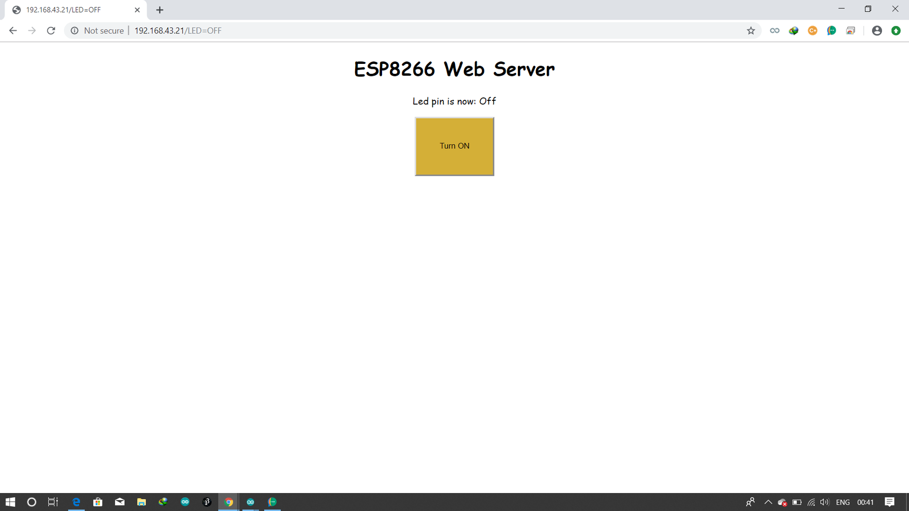
But before that, you can check some of our Home Automation Projects made using ESP8266 or ESP32: 1. Home Automation using NodeMCU & Alexa 2. Home Automation with Arduino IoT Cloud using ESP32 3. Home Automation using ESP8266 WebServer 4. Home Automation using Blynk & NodeMCU 5. Home Automation using Google Firebase & NodeMCU 6. In this article, we will explore how to create an IoT home automation system using the ESP8266 microcontroller board, along with the BC547 transistor and 5V relay. This guide will provide you with a step-by-step approach to building your own smart IoT home Automation system using ESP8266 enabling you to control appliances and devices from anywhere.
MQTT ESP8266 Home Automation Project 2021 Circuit Diagram
This is the complete circuit diagram for this home automation project. I have explained the circuit in the tutorial video. The circuit is very simple, I have used the GPIO pins D1, D2, D5 & D6 to control the 4 relays.. And the GPIO pins SD3, D3, D7 & RX connected with push buttons to control the 4 relays manually.. I have used the INPUT_PULLUP function in Arduino IDE instead of using the pull

You can create an ESP8266-based home automation system that controls your home's lighting system, automatically turning the lights on and off. The cost depends on the complexity of your home automation and the number of devices you want to control. But generally, ESP8266-based home automation is affordable and cost-effective. In this IoT project, I have explained how to make an Arduino Cloud ESP8266 home automation system to control appliances through the internet from anywhere in the world. With this Internet of Things project, you can control 4 relays from the Arduino IoT Cloud dashboard, Google Home/Alexa app, and manual pushbuttons. Everyone tries to automate home in some manner then that can be remote controlled or manual. And which makes life easier for them. There are man techniques to control the home appliances from remotely. In this article we will see how to make home automation using mqtt protocol and esp8266.
