ECG Signal Processing Using STMicroelectronics Nucleo Board Circuit Diagram The Arduino continuously samples the analog signal from the A0 pin, which represents the real-time ECG waveform. This signal is then converted from analog to digital format by the Arduino's ADC (Analog to Digital Converter) for further processing. The digitalized ECG data is transmitted to the computer via a USB connection.
An electrocardiogram signal can be simulated using a waveform generator. Select the appropriate in-built ECG waveform function using the user interface. The signal should have a low amplitude input of 1 - 5 mV and a frequency of around 1.2 Hz. Connect the generator to the input terminal of the integrated circuit.
Electrocardiography, Simple ECG Circuit Using OP Circuit Diagram
ECG signal will vary in amplitude depending on the placement of the recording electrodes and the individual, but are typically on the order a few millivolts when recording from the wrists. (While it is not necessary for this setup, signal amplitude can be increased by placing electrodes on the chest, but the trade-off is noise from lung movement.)- To interface the AD8232 ECG Module with Arduino, make connections according to the given table/Circuit diagram. Use the Arduino IDE to upload this code. Go to tools>Serial Plotter in the Arduino IDE and set the baud rate to 9600. . You may view the results in the form of a graph on the Arduino IDE plotter after the code has been uploaded. Our EKG circuit includes a standard instrumentation amplifier (INA 128) with a simple low-pass RC filter and a high-pass RC filter, both designed using the standard LM741 ICs. The filters can be connected in sequence without a DC offset since we are using a simple DC battery power as the power source, which introduces insignificant DC shifts.
I made this circuit for general biopotential measurements, but once you figure out the specific signal you want to measure, you'll probably need to make more changes. For ECG, the amount of gain used is probably sufficient, but for EEG or a more sensitive signal, you'll probably need some more gain. I would recommend adding a few bandpass filters.
Make Your Own Electrocardiogram (ECG) : 6 Steps Circuit Diagram
In 2019 I released a YouTube video and blog post showing how to build an ECG machine using an AD8232 interfaced to a computer's sound card. At the end of the video I discussed how to use a 555 timer to create a waveform roughly like an ECG signal, but I didn't post the circuit at the end of that video. This tutorial is an in-depth guide on how to make your own simple EEG circuit. Along with monitoring brain wave concentration, the final circuit can also be used as an ECG, as a way to see your heartbeat trace. The circuit will use 3 electrodes - 2 to measure a voltage difference across your scalp, and one as a reference to ground.
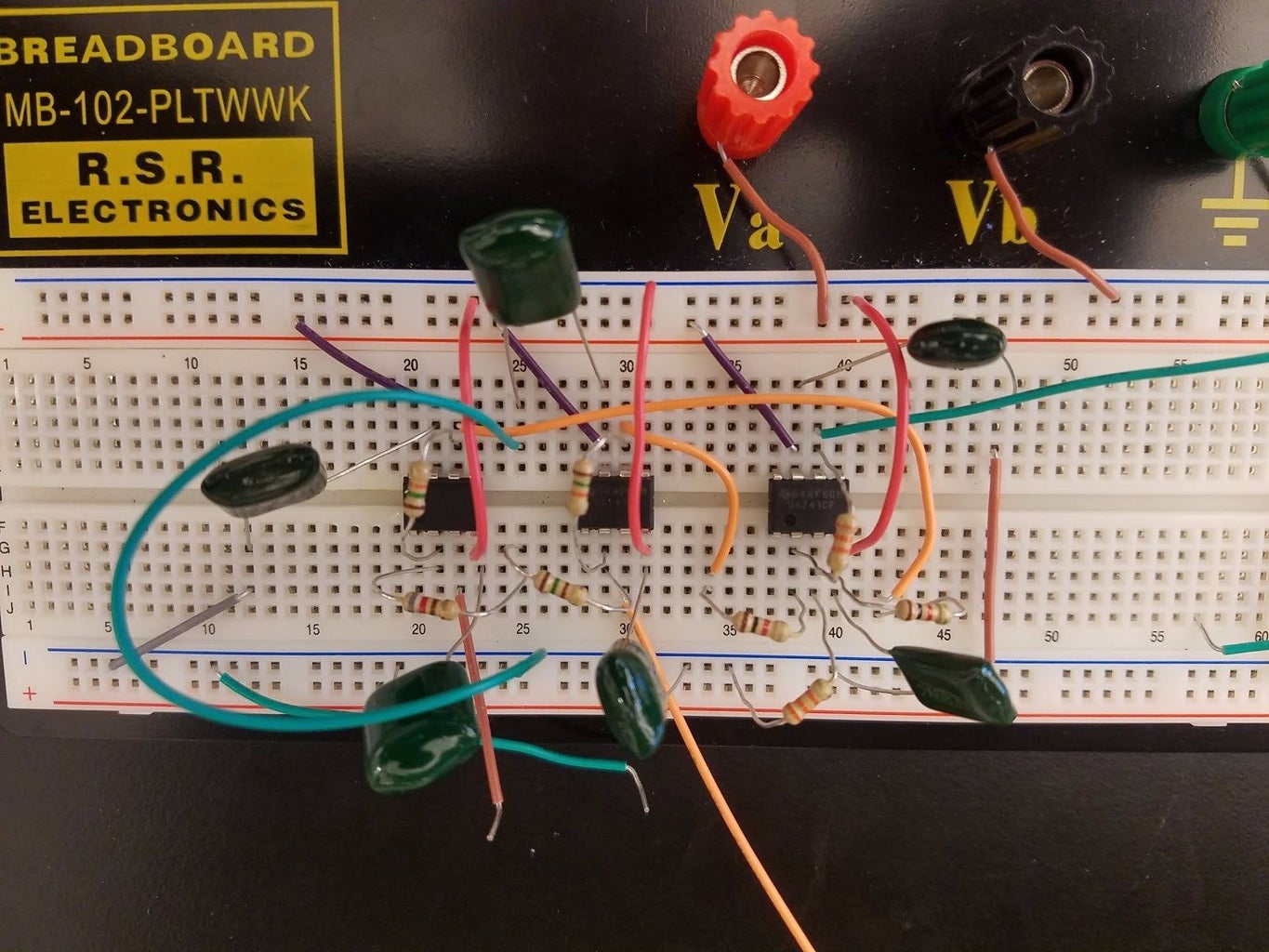
Featuring an instrumentation amplifier made up of three 741 op-amps and an assortment of resistors.#ecg #circuit