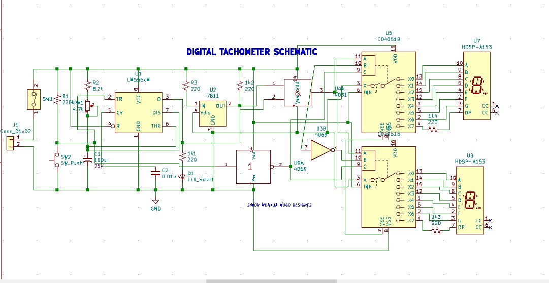
Digital Tachometer Circuit Diagram This article is about a contactless digital tachometer using arduino. The speed of the motor can be also controlled using the same circuit. The RPM and all the other informations are displayed on a 16×2 LCD screen. The circuit diagram of the digital tachometer using arduino is shown below. Circuit diagram.
Digital Readout: Use an analog-to-digital converter (ADC) and a microcontroller to display the RPM on a digital display, such as an LCD or a 7-Segment Display. Step 5: Calibration Calibrate the tachometer circuit by measuring the output voltage at known rotational speeds and adjusting the components accordingly. Simply we have interfaced the IR sensor module with Arduino and the 16*2 LCD module for display. The IR sensor module consists of IR Transmitter & Receiver in a single pair that can work as a Digital Tachometer for speed measurement of any rotating object. The Tachometer is an RPM counter which counts the no. of rotation per minute. There are
Tachometer Circuit: How it Works and How to Make One Circuit Diagram
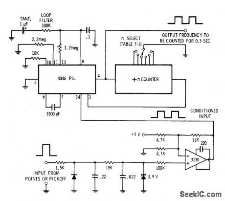
A digital tachometer circuit is a device that measures the rotational speed of a motor or other rotating object and displays the results in a digital format. To build a digital tachometer circuit, there are several key components that are required. Microcontroller: The microcontroller is the brain of the digital tachometer circuit. It receives Analog tachometer circuits use a dial-type interface and a needle to indicate the current readings of the engine speed. Again, these tachometers can't measure extra details like deviation and average. So, the analog tachometer uses an external frequency-to-voltage converter to measure the RPM. It also displays the converted voltage via an
A tachometer is an instrument that measures the rotational speed of a shaft or disk in a motor or other machine. Here we present the basic version of the tachometer that shows the revolutions per second (RPS) on a digital display. Fig. 1: Block diagram of the tachometer. Fig. 1 shows the block diagram of the tachometer. Step 2: Design the circuit. Next, you will need to design the circuit for your digital tachometer. Start by connecting the sensor to the microcontroller, which will be responsible for processing the signals and calculating the motor's speed. Connect the LCD display to the microcontroller to show the speed readings. This blog is based on Digital Tachometer using Arduino for measuring Motor Speed (RPM). Here we will discuss Introduction to Digital Tachometer using Arduino, Project Concept, Block Diagram, components required, circuit diagram, working principle, and Arduino code.

Detailed Circuit Diagram Available
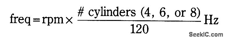
A tachometer is a device estimating the rotation speed of a disk or plate, as in an engine or other machine. The engine drives the wheel and generates pulses. These pulses are then read by a tachometer. This device generally shows the revolutions per minute (RPM) on an adjusted Analog dial, yet the digital tachometer shows are progressively normal.