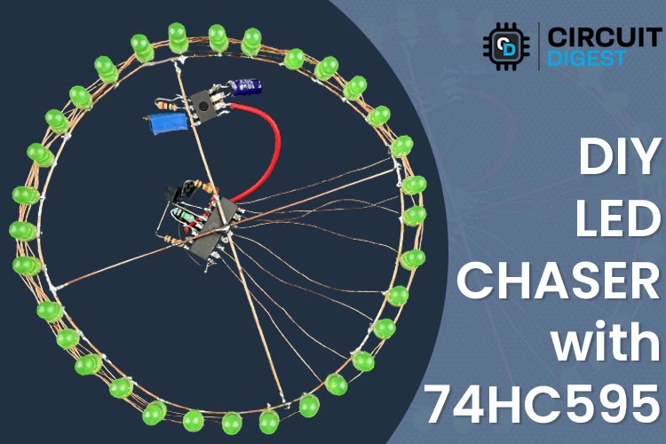
Create Circular LED Chaser using 74HC595 8 Circuit Diagram [NEW] LED Chaser Circuit Using 8 Bit Shift Register and 555 Timer IC | 555 Timer Projects | BC547In this video we are going to make a new LED chaser Circuit

The shift register then shifts the pulses to its output pins in a specific pattern, which can be programmed using the microcontroller. In addition to reducing the number of output pins required from the microcontroller, shift registers also provide flexibility in the LED chaser circuit design. The pattern of the LED lighting sequence can be A shift register is an electronic component that allows the user to control multiple outputs using a single input signal. Shift registers are commonly use in LED chaser circuits to control the pattern of LED lighting sequences. A Shift Register is basically a Serial-to-Parallel Converter IC. how to Control 16 LEDs with 74HC595 Shift Register | 16 Channel led light Chaser using 74HC595Code, Schematics and Proteus Simulation Download link:- https:/

LED Chaser With 74HC595 Shift Register Using Arduino Circuit Diagram
Well, you can make a nice 8 LED Scanner with a shift register IC. In this tutorial we'll be using the 74HC595 8 Bit Shift Register, and this is what we'll be making; Parts Required: Arduino Uno (Or Arduino compatible clone) Jumper Wires (Various colours and lengths) 1x 74HC595 8 Bit Shift Register 1x Breadboard 8x 220 Ohm Resisters 1. Arduino Uno to the control shift register. 2. Two shift registers 74hc595 for controlling the LEDs. 3. 16 LEDs as an output. 4. 16 resistors to protect the LEDs. 5. Breadboards to build the circuit on it. 6. Jumper wires for connection. If you want to learn how shift register work? Click on this Link Circuit Diagram with 200 LED Chaser Circuit. The basic reverse forward LED circuit using single LEDs can be studied elaborately in this LED scanner article, and the video can be witnessed below: How to Connect the LEDs. The following diagram illustrates the connection arrangement of the LEDs to the above circuit.

74HC595 8-Bit Shift Register Pinout . The 74HC595 is an 8-bit serial-in, parallel-out shift register IC that is commonly used to drive leds motor or any other electronic equipment.. PIN(Q0 - Q7) Output pin of the IC, that can be controlled serially. GND Connected to the Ground of the Circuit.. MR Master Reset: Resets all outputs as low. Must be held high for normal operation LED chaser circuit using shift register Hi, I am the Electronics Guy. In this tutorial I will teach you how to build a cool LED chaser circuit. I have modifi Project 1: LED Chaser using 74HC595 & Arduino. An LED chaser creates a visual effect where LEDs light up one by one in a sequential pattern, resembling a chasing motion. Variations can include adjusting the speed of the sequence or reversing the direction of the chase for added dynamics. We can use the following code with Arduino to develop LED
