Capacitors In Dc Circuits Lab Report Circuit Diagram To create a low-pass filter using an R and L, we can start with an RC high-pass filter as shown in Figure 4 and swap the C for an L. We can also take the same type of approach to design a high-pass filter if we start with a RC low-pass filter as shown in Figure 2 and replace the C with an L. Both examples are illustrated in Figure 6. Figure 6. Filters are circuits whose response is dependent on the input voltage's frequency. Many crucial tasks in a system can be carried out by filter circuits. While resistors, capacitors, and inductors can also be used to create filters, op-amps, resistors, and capacitors are the main components of most filter circuits.

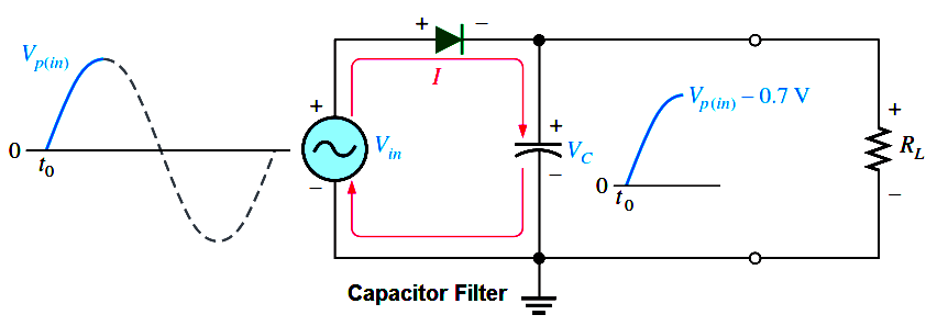
This high pass filter circuit project filters a frequency spectrum or any mix of frequencies. The frequencies below the cut-off frequency of the filter are blocked effectively by the capacitor C. This circuit has a resistor connected in parallel and a capacitor in series with the output. The principle involved : the reactance of the capacitor is inversely proportional to the frequency applied

Pass Filter Circuits Quickly Circuit Diagram
As proposed, to design a high-pass filter circuit quickly, the following formulas and the subsequent steps can be used for calculating the relevant resistors and capacitors. First, select an appropriate value arbitrarily for C1 or C2, both can be identical. Next, calculate R1 by using the following formula: R1 = 1 / √2 x π x C1 x Frequency
filter is usually equal to the total number of capacitors and inductors in the circuit. (A capacitor built by combining two or more individual capacitors is still one capacitor.) Higher-order filters will obviously be more expensive to build, since they use more components, and they will also be more complicat-ed to design.
PDF Basic Introduction to Filters Circuit Diagram
For this circuit, with the values chosen, we build a bandpass filter that has a passband from 1KHz to 10KHz. If modifying these frequencies, then the values of the resistors and capacitors need to change. Passive Bandpass Filter Circuit. The passive bandpass filter circuit that we will build with resistors and capacitors is shown below.
I explain how high-pass RC filters work using the falstad circuit simulator and a circuit which is similar to the one used with the low pass filters in a pre