Battery Power Conversion for Video Doorbell 6 Steps with Pictures Circuit Diagram IoT Doorbell Project Description: IoT Doorbell Project-you can call this project with different names e.g. IoT Doorbell or Wifi Doorbell or Wireless Doorbell or Smart Doorbell etc. Keeping in mind the Covid-19 "Corona Virus" situation going on all over the world, I decided to make a Wireless smart IoT Doorbell based on the Wifi and IR sensor.The Doorbells are among the most germ-infected Essentially, the doorbell has a teeny-tiny alternator. Pushing down on the button creates a mechanical force, and piezoelectricity uses this as a micro-power source to produce a low-power signal.
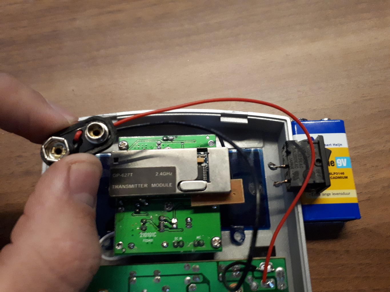
In order for the ESP8266 to hear when someone rings the doorbell, I used this board with a microphone on it made especially for Arduino. Surely there are other ways to detect when the doorbell is rung, but using the microphone has the great advantage that we do not have to make any changes to the electrical system.

STEM Activities for KS2: Make a Doorbell Circuit Circuit Diagram
3. Battery-powered Doorbell Circuit Diagrams. Battery-powered wireless doorbell circuit diagrams are designed to operate using batteries as the power source. These diagrams include components such as a battery-operated transmitter, a receiver, and a speaker or chime. Activity: Make a doorbell circuit. In this activity pupils will assemble a doorbell circuit. This develops understanding of how switches are used and how electrical circuits function. This could be used as a KS2 engineering activity or as a design and make or general STEM project.

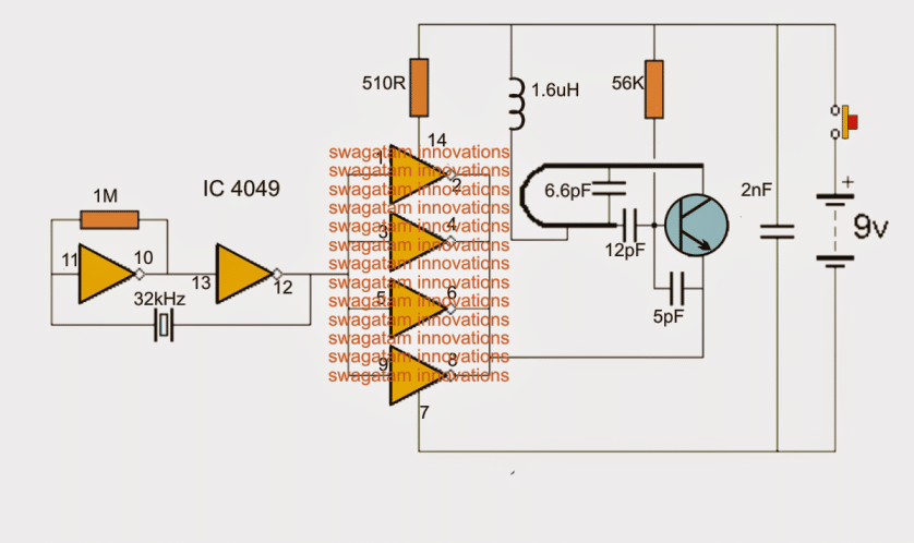
Learn how to build a smart latching circuit that toggles any electronic device ON/OFF with just one push button! This simple, no-IC design uses an IRF Z44 MO This Door Bell may also used by main Door Bell of the house. This Door Bell circuit contains two normal NPN transistors (BC 547) and a musical transistor BT 66 T19L.This circuit consumes 3-4.5V.The amount of volume of the Door Bell is increased by increasing the Voltage level. Existing hard-wired and powered doorbell. Concept & Diagram: The concept is simple. Mechanical doorbells contain an electromagnet that fire when the doorbell button is pressed (circuit is closed). This method uses the magnetic field produced when the button is pressed along with a N/C reed switch to trip a z-wave sensor! Check it out:

IoT Doorbell Project, Wifi Doorbell, Smart doorbell without contact ... Circuit Diagram
Touchless Door Bell - Free download as Word Doc (.doc / .docx), PDF File (.pdf), Text File (.txt) or read online for free. The document describes a touchless doorbell circuit that uses an IR transmitter-receiver pair and sensor. When the sensor detects movement of a hand in front of the doorbell, it automatically rings a buzzer without the need to physically press a button.