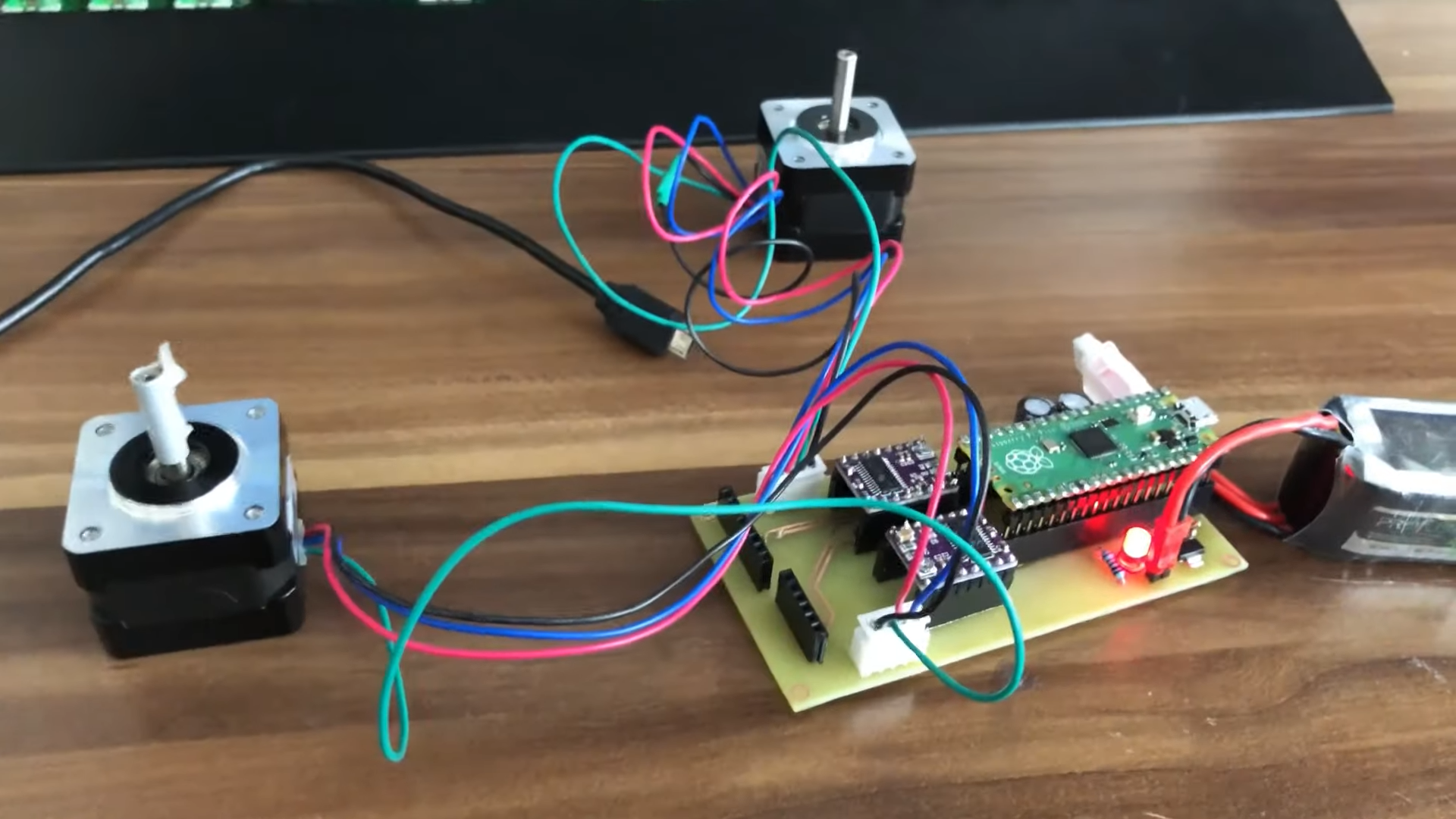
Balancing Robot robotics maximintegrated Circuit Diagram We will show you how you can create your own self-balancing robot that can also avoid obstacle along its path. We will be using a Arduino Uno board and a MPU6050 accelerometer-gyroscope. You will understand how the MPU6050 works with an Arduino Uno, measure the inclination angle of the robot, PID loop to make the robot stay balanced.

This is a circuit diagram for a self-balancing robot.\\n\\nThe circuit consists of two Dc motors, preferably gear motors with an embedded encoder (for position control), an arduino board and finally a MPU-6050 6 axis gyroscope and accelerometer. Evidently, in the circuit diagram, i have placed a another gyroscope as the mpu-6050 isn't available
DIY Self Balancing Robot using Arduino Circuit Diagram
1. The physical structure of the robot is modified, so that the robot is much more robust and easier to control. The very early version is shown in the first picture, while the current version (2.0) is shown in the second picture. 2. An illustration of torque equilibrium of the robot is added. 3. A new program is written for PID tuning.

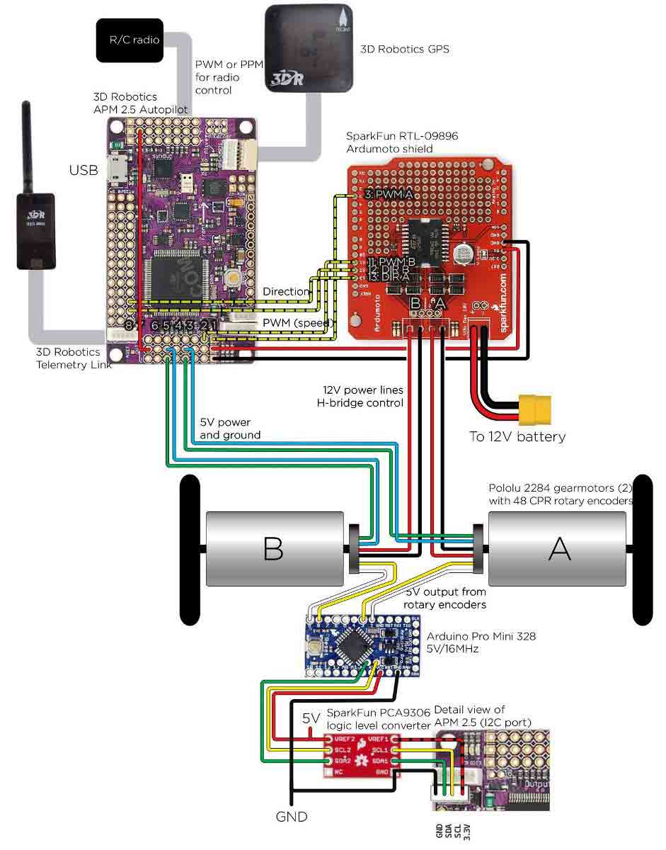
Making the connections for this Arduino based Self balancing Robot is pretty simple. We just have to interface the MPU6050 with Arduino and connect the motors though the Motor driver module. The whole set-up is powered by the 9V li-ion battery. The circuit diagram for the same is shown below.
DIY Self Balancing Robot DC Motors Bluetooth HC Circuit Diagram
Circuit Connection of Self Balancing Robot. Making the connections for this Self Balancing Robot using Arduino is pretty simple. We just have to interface the MPU6050 accelerometer with Arduino and connect the motors through the Motor Driver Module. The whole set-up is powered by a 9V battery.