Automatic water level controller Circuit Diagram But I have to control the water level in the tank is fixed, is water must not out or overflow, which is a waste of time look at the pump. I have the ideal to create this automatic water pump controller project. Main ideas. When the water a full tank. This circuit controls the pump stopped working. Then we use the water out. In this video I am going to show you how to make an Automated Water pump control system using several electronic components including PCB Etching, Drilling a 1) Simple Automatic Water Level Controller Using Transistors. Please find the attached circuit for a very simple and cheap water level controller. This design is only a basic portion of my own marketed product having unsafe voltage cutoff, dry run cut off and LED & alarm indications and overall protection.
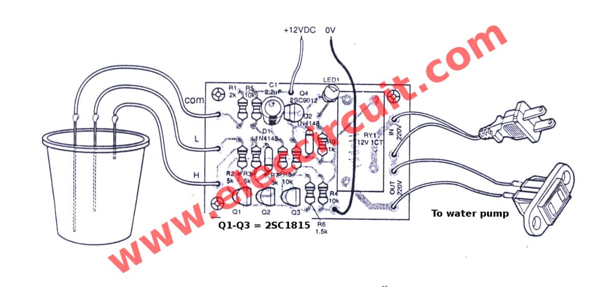
Pin#2 is placed at the bottom of the water tank to detect when the water is too low. If the water covers the sensor (a 2-pin plug), pin#2 stays at the full voltage level, keeping pin#3 inactive. When the water level falls and uncovers the sensor, pin#2 loses its voltage. It uses readily-available, low-cost components, and is easy to build and install on the over-head tank (OHT) to prevent wastage of water. Fig. 1: Simple automatic water level controller. The circuit works off a 12V battery or 230V AC mains using a 12V adaptor. A Simple Automatic Water Level Controller with BJTs Only Heres the circuit I've attached for a really basic and affordable water level controller. It's just a simple part of a bigger product I sell that has a bunch of safety features like cutting off when there's unsafe voltage, stopping if there's no water to pump, and giving warnings

Simple Automatic Water Circuit Diagram
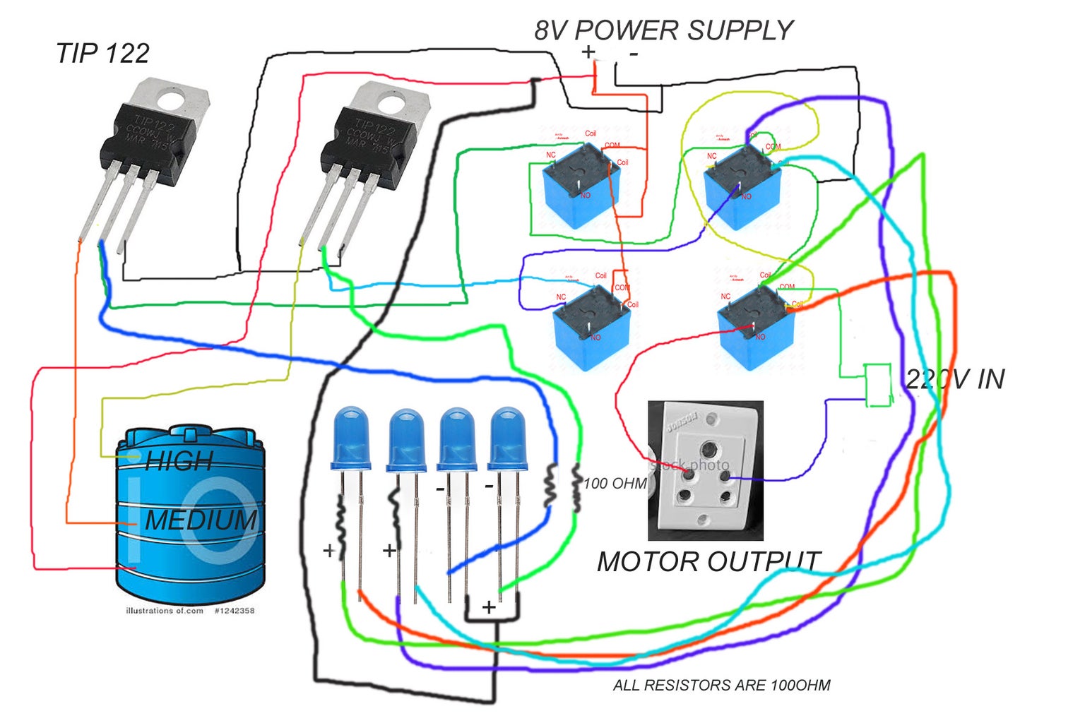
How to Make Fully Automatic Water Pump Controller | Water Level Indicator and Pump ControllerIn this video, you will learn how to make a water pump controlle
Here is a simple automatic water-level controller for overhead tanks that switches on/off the pump motor when water in the tank goes below/above the minimum/maximum level. The water level is sensed by two floats to operate the switches for controlling the pump motor. Previously we designed the simple automatic water pump controller circuit. The Design. The proposed water level controller circuit using a float switch is basically a semi-automatic system where the pump is started manually by press of a button, once the water level reaches the brim of the tank, the operation is switched of automatically by means of a float switch.
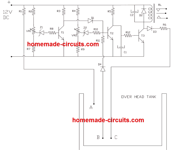
Water Level Controller Circuit using only Transistors Circuit Diagram
As the name depicts, a water level controller is an automatic device used to monitor a particular level of water (for example in an overhead tank) and restrict it from exceeding the limit. The simple circuit design for such a controller shown here may be easily built and installed and may relieve you from the headache of manually operating the
