audio effect circuit Audio Circuits Nextgr Circuit Diagram WHAT IS THISLearn how to make a DIY frequency generator circuit using only a couple of components. RESOURCES Frequency Generator Schematic - https://drive
This audio frequency generator is a triggered signal generator. When a positive pulse of about 6 volts (minimum) is fed to the circuits input , a modulated audio signal comes out of the output. The signal pattern is similar to a bird's chirp. The pulse width of the trigger signal must be a minimum of 2.5 miliseconds. Sine, square, and sawtooth wave generators are essential circuits in synthesizers and electronic test equipment. Audio filters can be used to set frequency cutoffs or make sound effects. Ready to dive in? Check out the tutorials below! How to Build an Audio Mixer.
Full DIY Project - Electronics For You Circuit Diagram
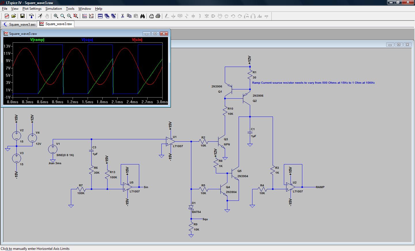
1) Using IC 4049. Using only one low-cost CMOS IC 4049 and a handful of separate modules, it is easy to create a robust function generator that will provide a range of three waveforms around and beyond the audio spectrum.. The purpose of the article was to create a basic, cost-effective, open source frequency generator that is easy to construct and used by all hobbyists and lab professionals. This is a simple function generator that works in the audio frequency range. It can be useful for amplifier testing, experimentation in DSP. Fig. 1: Author's prototype for Arduino based frequency generator. Circuit diagram of the sine, square and ramp Arduino-based frequency generator is shown in Fig. 2. It is built around an Ardunio Uno
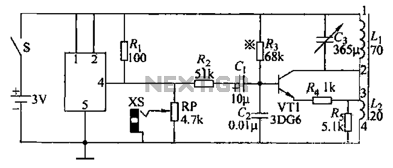
The counter circuit will count a lot. The voltage controller of the frequency generator will rise very fast. The oscillation of sound, it will be fast, such as birds singing loud that "jip..". In the opposite, if is a low-frequency signal, the oscillation of sound will slow down became the siren go out. After the idea to create the circuit
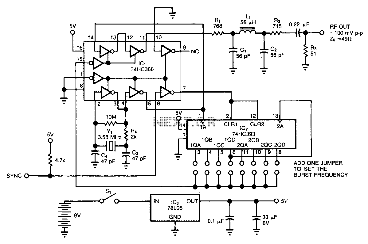
Audio Signal Generators and Filters Circuit Diagram
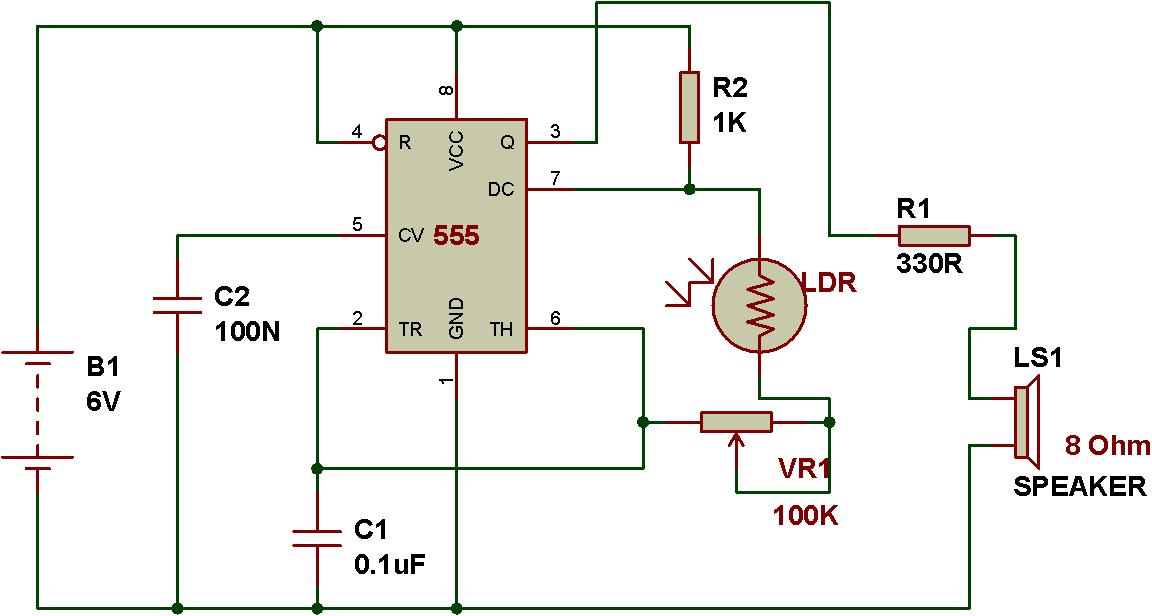
The audio frequency generator circuit diagram is a powerful tool for anyone looking to create custom sound effects and audio applications. By manipulating the circuit's components, it is possible to generate a wide range of sounds from high-pitched tones to low-frequency rumbles. In fact, with these diagrams, you're able to unlock a world Working Explanation. The operation of this circuit is based on the working principle of a self-triggering oscillator (astable multivibrator), performed by a 555 precision timer circuit (NE555).When the circuit is powered on, The values of resistors (R1, R2) & capacitors (C1, C2) on the left side of the circuit set the pitch of the output tone coming from the audio transducer (loudspeaker Creating an audio signal generator circuit diagram may seem intimidating and complicated, but with a little bit of knowledge and some practice, anyone can gain the skills necessary to get it done. By following this guide and understanding the basics, it's possible to create your own audio signal generators and reap the many benefits they can offer.
Below mentioned are the steps how to build An audio frequency SCR signal generator circuit : Identify Components: Gather all the required components listed above. Circuit Layout: Plan the layout of the components on your breadboard or PCB. Ensure you have space for the components and can make the necessary connections. Connect the Thyristor or SCR: