Analog to Digital Converter Block Diagram Types Its Applications Circuit Diagram A Digital to Analog Converter (DAC or D-to-A)is a device that converts digital codes to an analog signal. There are many categories of DACs. Some of these categories include sigma-deltaDACs, pulse width modulators, interpolating and high speed DACs. In this paper the focus will be on the interpolating and high speed DACs. What is DAC (Digital to Analog Converter)? Digital to analog converter is an electronic circuit that converts any digital signal (such as binary signal) into an analog signal (voltage or current). The digital signal such as the binary signal exist in the form of bits & it is the combination of 1's & 0's (or High & low voltage levels). 12.4.2: Digital-to-Analog Converter Integrated Circuits. There are many possible applications for digital-to-analog converters, and a number of different chips have evolved to meet specific needs. Generally, you can group these into specific classes, such as high speed, high resolution, or low cost. We will examine three representative types.
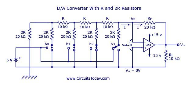
The R2R Ladder is a resistor network that converts digital signals to analog signals (DAC). R2R refers to the resistor values used in this network, where R and 2R represent specific resistance values, such as 1000 ohms and 2000 ohms, respectively. It is used in audio equipment, such as CD players and sound cards, to convert digital audio signals into analog voltages for playback. It is also
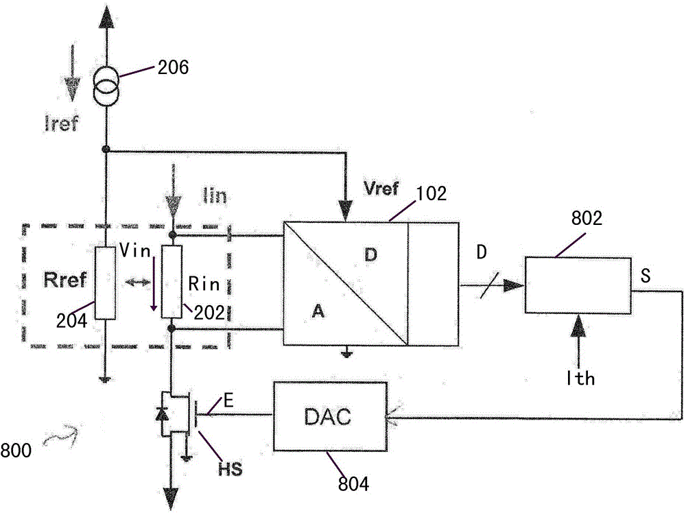
Digital to Analog Converter Circuit Diagram
Operational Amplifiers such as the inverting op-amp circuit uses negative feedback to both reduce and control its very high open-loop gain, A OL.It does this by feeding back a small fraction of its output signal back to its input terminal. For an inverting amplifier, the input voltage V IN is connected directly to its inverting input via a suitable input resistor R IN and that the inverting In this lab you will build an op-amp circuit to convert digital numbers to analog voltages. This circuit is called a digi-tal-to-analog converter, or DAC. This circuit will be used again in Experiment 11 as the core of an analog to digital converter (ADC). Experiment Objectives: • Learn the principles of digital to analog and analog-to
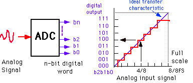
There are two basic type of converters, digital-to-analog (DACs or D/As) and analog-to-digital (ADCs or A/Ds). Their purpose is fairly straightforward. In the case of DACs, they output an analog voltage that is a proportion of a reference voltage, the proportion based on the digital word applied. In the case of the ADC, a digital representation

Digital to Analog Converter (DAC) Circuit Diagram
A digital-to-analog converter (DAC, D/A, D2A or D-to-A) is a circuit that converts digital data (usually binary) into an analog signal (current or voltage). One important specification of a DAC is its resolution. It can be defined by the numbers of bits or its step size. Digital to Analog Converter using the Summing Amplifier Here is a circuit schematic for a pulse-width modulated DAC. Here the counter is used to produce a count value A that ramps up linearly in a sawtooth manner. The digital value we want to convert to analogue value is data_in, which is stored as B in the input register. A digital comparator circuit compares this input data with the counter value There are two main types of digital to analog converters that we'll talk about in this post. Types of Digital to Analog Converters (DACs) Binary-Weighted Digital to Analog Converter. Below we have a simple, 4-bit binary-weighted digital to analog converter (a.k.a. weighted resistor DAC).