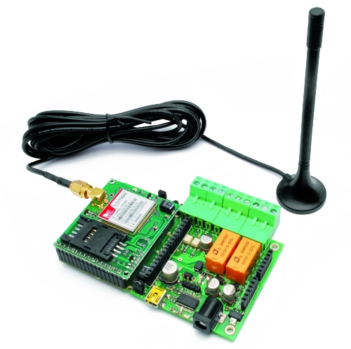
An Android app to manage the GSM Remote Control Circuit Diagram To top it all off, the module supports quad-band GSM/GPRS networks, which means it will work almost anywhere in the world. Hardware Overview. At the heart of the module is a SIM800L GSM cellular chip from Simcom. The operating voltage of the chip ranges from 3.4V to 4.4V, making it an ideal candidate for direct LiPo battery supply.

Overview. In this article we will learn how to use SIM7600 GSM GPS 4G LTE Module with Arduino & use AT Commands to make receive call or send receive SMS or Internet Connection.. Earliier we use 2G GSM Module like SIM800/900 and also A9G GSM GPS module. As we know the 2G GSM/GPRS is in the stage of closing in most countries or regions like Australia & Canada. But there are indeed some projects It allows the user to send an SMS or make a call by sending specific characters ('s' for SMS, 'd' for dialing) through the Arduino's Serial Monitor. The GSM module is configured to send an SMS to a specified phone number with the message "I am SMS from GSM Module" when 's' is received and to dial a specified phone number when We use SIM900 GSM Module - This means the module supports communication in the 900MHz band. We are from India and most of the mobile network providers in this country operate in the 900Mhz band. THANK'S BEFORE,I WANT TO DESIGN ARDUINO BASED REMOTE PATEINT MONITORING SYSTEM BY USING GSM ,PLEASE WOULD YOU HELP BY PROGRAMMING C CODES FOR

Interface GSM Module to Arduino Circuit Diagram
Power Supply: Connect the VCC pin of the SIM808 module to a 3.7V LiPo battery or a regulated 4V power supply. Ensure the ground is connected to the Arduino's GND. Serial Communication: Connect the TXD pin of the SIM808 to the RX pin (Pin 0) of the Arduino and the RXD pin to the TX pin (Pin 1). GPS Antenna: Attach an active GPS antenna to the GPS_ANT pin for accurate positioning.

The Terminal Adapter establishes communication between the Terminal Equipment and the Mobile Termination using AT commands. The communication with the network in a GSM/GPRS mobile is carried out by the baseband processor. Applications of GSM Module or GPRS Module. The GSM/GPRS module demonstrates the use of AT commands. They can feature all the

How to Use SIM800L GSM Module: Examples, Pinouts, and Specs Circuit Diagram
GSM SIM900A Arduino Tutorial (Easy 4 Step): Introduction to SIM900A SIM900A is a GSM module that function like phone. It can send a message, call a phone number and use GPRS to send data. Don't forget to use BOTH NL&CR in arduino Serial monitor option. Test the connection by type "AT" and then enter. If the arduino reply "OK
Power Optimization: Enable GSM sleep modes to conserve battery. Firmware Updates: Implement OTA (Over-the-Air) updates for the microcontroller/GSM module. Monitoring: Track data usage and server uptime. Tools & Tips: GSM Modules: Use modules with MQTT/HTTP support (e.g., SIM7600). Security: Use VPNs or private APNs for sensitive applications Q: Can the SIM800c module connect to a 5V logic microcontroller directly? A: No, a level shifter is recommended to convert the 5V logic level to the 3.3V level required by the SIM800c module. Q: How can I send an SMS using the SIM800c module? A: Use the AT command AT+CMGS="phone_number" followed by the message and a Ctrl+Z character to send an SMS. This circuit is designed to interface an Arduino UNO with a SIM800L GSM module, PIR sensor, photocell, buzzer, and multiple LEDs. It is likely intended for environmental monitoring and alerting, with the capability to communicate over GSM for remote notifications. The LM2596 module provides voltage regulation for the GSM module.