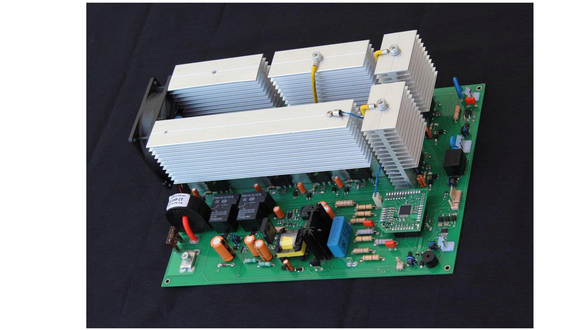
All about voltage stabilizer How it works and How to choose the best Circuit Diagram The proposed circuit of a simple high capacity automatic voltage stabilizer circuit is easy to understand. All the opamps are arranged in standard voltage comparator modes. The presets P1 to P7 can be adjusted as per the required tripping points, which will correspond to the output SSR switching and the subsequent transformer tap selections. About Press Copyright Contact us Creators Advertise Developers Terms Privacy Policy & Safety How YouTube works Test new features NFL Sunday Ticket Press Copyright

The suggested easy automatic voltage stabilizer circuit might be set up with the following procedures: In the beginning do not hook up the transformers to the circuit. Making use of a adjustable power supply, power the circuit across C1, the positive goes to the terminal of R1 while the negative goes to the line of D2's cathode.
Automatic Voltage Stabilizer Circuit using SCR/TRIAC Circuit Diagram
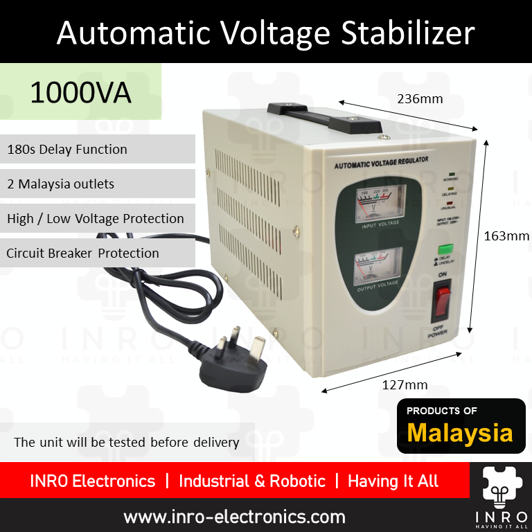
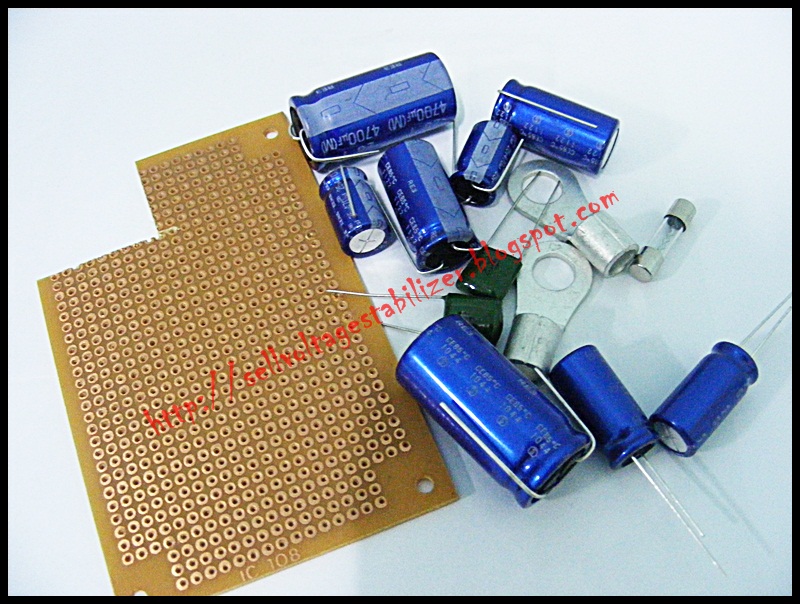
In this instructables, I will show you how to make automatic voltage stabilizer using Arduino NANO that will show AC voltage, watt, steps, transformer temperature & auto fan on-off for cooling. This is 3 steps Automatic Voltage stabilizer. My configuration. 1st steps is normal/output . 2nd steps adds 20 V to output . 3rd steps adds 50 V to If precise voltage control is critical, a resistor divider might be a better option. If simplicity and cost are your priorities, a zener diode is a good choice. Transformer Relay Wiring Diagram Parts List. You will require the following components to make this homemade automatic mains voltage stabilizer circuit: The next page covers the circuit and the construction details of this automatic voltage stabilizer circuit. Circuit Description. The functioning of this simple voltage stabilizer circuit may be understood from the following points: Referring to the figure (Click to Enlarge) we see that Transistor T1 forms the main active part of the entire circuit.
The present circuit of triac controlled AC voltage stabilizer is outstanding in its performance and is almost an ideal voltage stabilizer in every respect. As usual the circuit has been exclusively designed by me. It is able to control and dimension the input AC mains voltage accurately through 4 independent steps.
How to make automatic voltage stabilizer step by step Circuit Diagram
How to Set Up the Circuit. The discussed simple automatic voltage stabilizer circuit may be set up with the following steps: Initially do not connect the transformers to the circuit, also keep R3 disconnected. Build a simple automatic voltage stabilizer to protect electronics from high and low voltage. A voltage stabilizer is a device used to detect fluctuating voltage levels and rectify them, ensuring a relatively stable output at the point where the load is connected. In this article, we will explore the design of a simple automatic mains AC Learn about the entire building process of this special solid state mains voltage stabilizer. Any piece of equipment at its output will receive good four-step voltage stabilization from the suggested setup of a triac-controlled AC voltage stabilizer. Its efficiency is additionally improved by the absence of moving components.