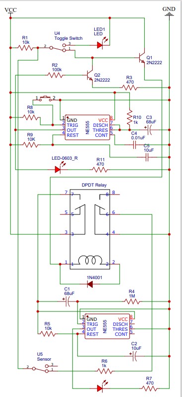
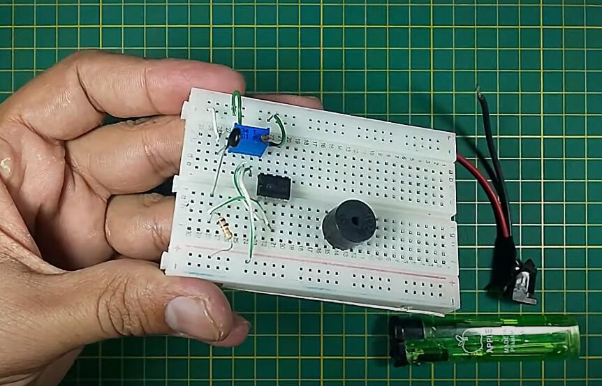
Alarm System Circuit Diagrams Circuit Diagram Hi , This video is to show you how to make a simple beeping buzzer circuit, which can be used as alarm. Download the circuit diagram - https://drive. To build our simple alarm circuit, you'll need the following components: Breadboard: A platform for building and testing circuits. 9V Battery: Power source for the circuit. Battery Snap: Connects the battery to the circuit. Push Button Switch: Activates the alarm. Resistor (220 ohms): Limits current to the LED. LED (any color): Indicates the Important Post: Pull Pin Security Alarm Circuit. Working of Security Alarm Circuit: S1 and S2 are the two switches that are used in the circuit so that both can be put in two different places i.e. one of them can put in front of the locker while another one can be placed on the front door. When the switch S1 is pressed diode D1 which is linked

Step 5: Test the Alarm System. Once the sketch has been uploaded successfully, test the alarm system by moving in front of the PIR sensor. You should hear the buzzer sound and see the LED light up when motion is detected. Customize the Alarm System. Now that you have a working Arduino alarm system, you can customize it to fit your specific needs. It is simple, make two of the last circuits, one will have a timing capacitor in series with the 100k feedback resistor and the second circuit will be positioned across the points where the alarm is indicated, meaning the circuit with the timing capacitor becomes responsible for powering the second circuit…
9 Burglar alarm circuit ideas Circuit Diagram
Learn how to make a simple motion-activated alarm using a PIR sensor, 470-ohm resistor, 147 transistor, and a buzzer. This easy DIY electronics project is pe
Simple burglar alarm circuits. At this period the economy not good, Make have steal plentiful. We come to try build the circuit steal model to is simple better. The Alarm Sound (Super Bell) loud forever until will cut power supply to go out. When the Switch of the magnet Senate was opened or strip metal torn. The R1 stand gives to get the To make a simple alarm circuit, you need to know the basic parts. These parts are key for the circuit to work well. They also help add extra features to make the circuit better. As we keep adding tech to circuits, smart alarm systems will lead the way in safety and ease of use. They will meet the needs of today's security challenges. Fine-Tuning Your Alarm System. Once you've successfully built and tested your simple alarm circuit, consider some enhancements: Adjust Sensitivity: Most PIR sensors have adjustable sensitivity settings; play around with these to suit your environment. LED Indicators: Adding LEDs can provide a visual cue that the alarm circuit is active.
Easy Home Security DIY - YouTube Circuit Diagram
When writing the code we will not to use any libraries. I set the maximum distance to 100 cm for example purposes. However you can choose what ever distance you would like to set as the maximum distance where the buzzer will go off. Just make sure if you are changing one number then just check the rest of the code and make sure the numbers make