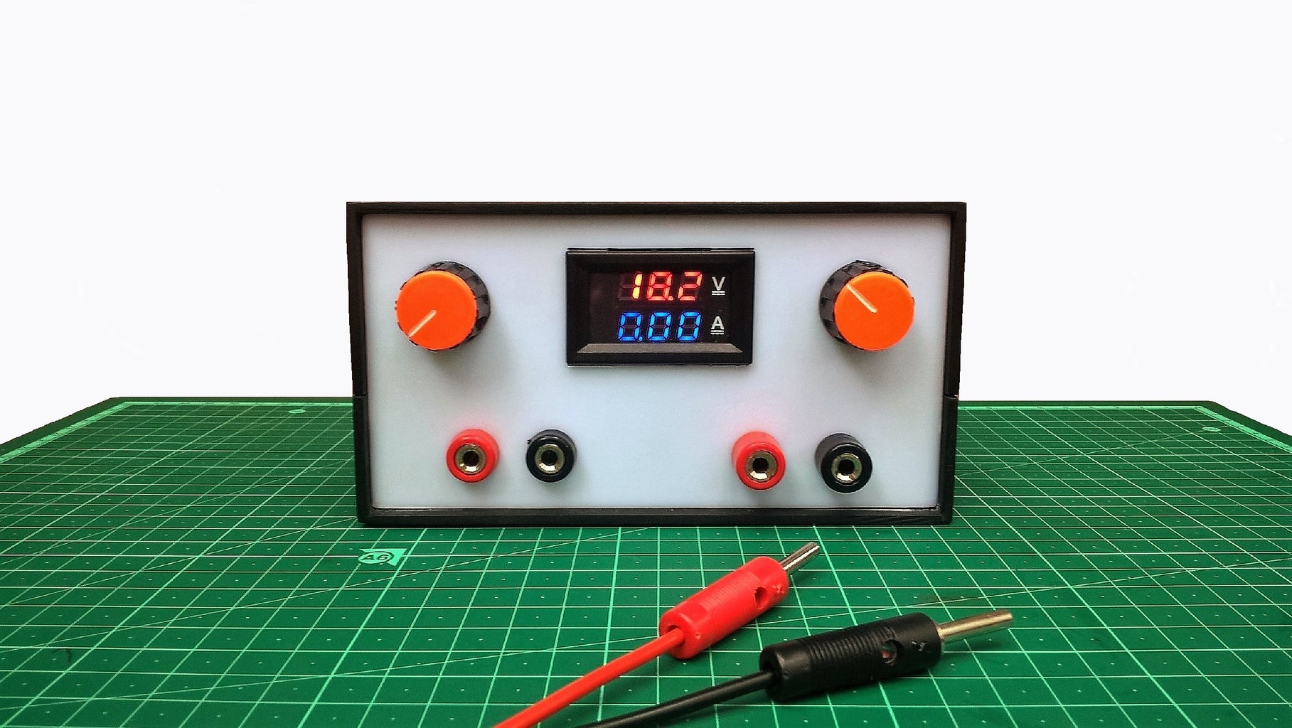
Adjustable Power Supply DIY Battery Charger Circuit Diagram 0 - 50v 0 - 40A Variable Power Supply // how to make adjustable power supply at home👉DC Motor - https://amzn.to/49zYn3c👉 Transformerhttps://amzn.to/43w26vv I easily get continuously adjustable output voltage (1-30V) and current (0-6A), which is pretty enough for circuit testing and other things.I'm also using 7805 voltage regulator IC for 5V constant voltage and current. This Power Supply Has Following Features: Input Voltage 12V DC. Input Current 3A. Output Voltage (1-30V) Continuously Adjustable.
V in is the input voltage.; V out is the output voltage.; I out is the output current.; For example if V in = 12V, V out = 5V, and I out = 1A, then power dissipated by the LM317 would be:. P diss = (12V - 5V) * 1A = 7W. Adding a Current Control Feature . The figure above shows, how the IC LM317 can be effectively used for producing variable voltages and currents, as desired by the user. At the same time a few basic modifications will make the supply offer as much as 40 volts at 1.25 amperes. The supply voltage is adjustable between zero and' the highest available, and current limiting can also be adjusted across the stipulated full range. The mode of operation of the power supply is indicated by means of two LEDs. The LM317T variable voltage regulator also has built in current limiting and thermal shut down capabilities which makes it short-circuit proof and ideal for any low voltage or home made bench power supply. The output voltage of the LM317T is determined by ratio of the two feedback resistors R1 and R2 which form a potential divider network
Making an Adjustable Voltage, Current Power Supply Circuit Using ... Circuit Diagram
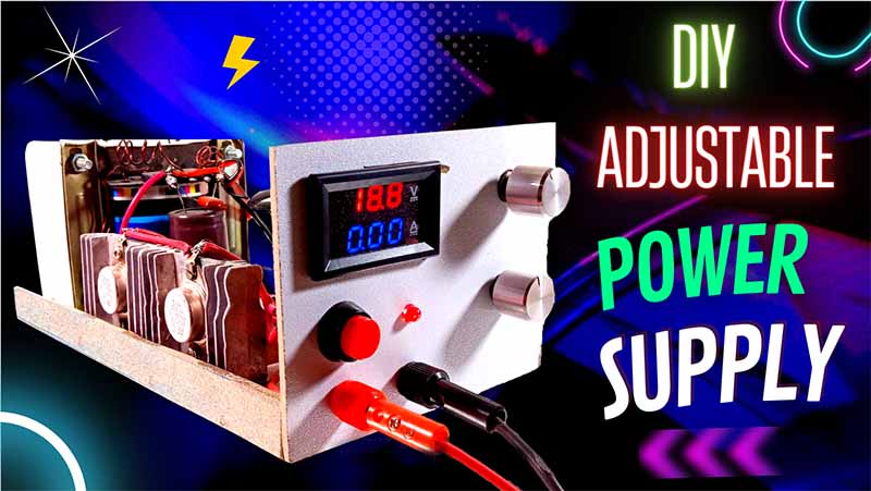
In this video, learn how to make a DIY variable power supply that allows you to adjust voltage for different electronics projects. We'll guide you through th Welcome to this tutorial on designing a variable power supply with adjustable voltage and current using LM317 IC, BD139 and TP3055 transistors. In this tutorial, I will walk you through the steps involved in designing this circuit, including the schematic diagram and the necessary components.
![How to make adjustable voltage simple dc power supply [DIY] Circuit Diagram](https://i.ytimg.com/vi/EZ1E8YfTVD8/maxresdefault.jpg)
The base resistor of T3 can be removed, since it is not required. How it Works. A keen look at this 2N3055 based variable voltage current power supply circuit using transistor 2N3055 reveals that it's actually only an ordinary stabilized power supply circuit, however it yet still provides you with the proposed features very efficiently.The voltage variations are made by using the preset P2 Every transistor in the diagram needs to have a minimum breakdown voltage of 55 volts. Variable power supply with high current capabilities. In this circuit for a high current linear power supply, a 2N5686 transistor is utilized instead of 2N3055 to enable a minimum current delivery of 10 amps.