Active Low Pass Filter Graph Circuit Diagram In general, the first-order low-pass filter finds wide use in several applications, including audio circuits, control systems, power electronics and more. Its simplicity makes it a popular choice for filtering signals with relatively low attenuation needs at higher frequencies. The low pass filter made with an operational amplifier

How to Build Audio Filter Circuits Graham Lambert 3 6 min read Learn how to build four different audio filters - high-pass, low-pass, band-pass, and notch filters. The low pass filter calculator helps you design and build a low-pass filter circuit, with support for passive (RC and RL) as well as active (op-amp based {in} v in — that's why it's called an "inverting filter". For some circuits (like audio systems) this effect doesn't matter much (as speakers don't care about polarity) but in other
Low Pass Filter Calculator Circuit Diagram
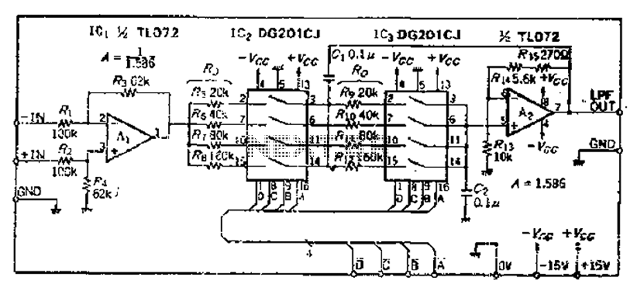
The following images depict the standard opamp based low pass filter circuits. The first one needs to be powered by a dual supply, and the second one works using a single supply voltage. Designing a Customized Low Pass Filter Circuit The most useful filters with ease of use and best all-around performance are the Sallen Key active filters. Sallen Key filters are two-pole filters, meaning they have two reactive components (capacitors). All of the circuits below are based on this design. Low Pass Filter. In a low pass filter, frequencies above a certain point are blocked: Active Low Pass Filter Example No1. Design a non-inverting active low pass filter circuit that has a gain of ten at low frequencies, a high frequency cut-off or corner frequency of 159Hz and an input impedance of 10KΩ. The voltage gain of a non-inverting operational amplifier is given as:

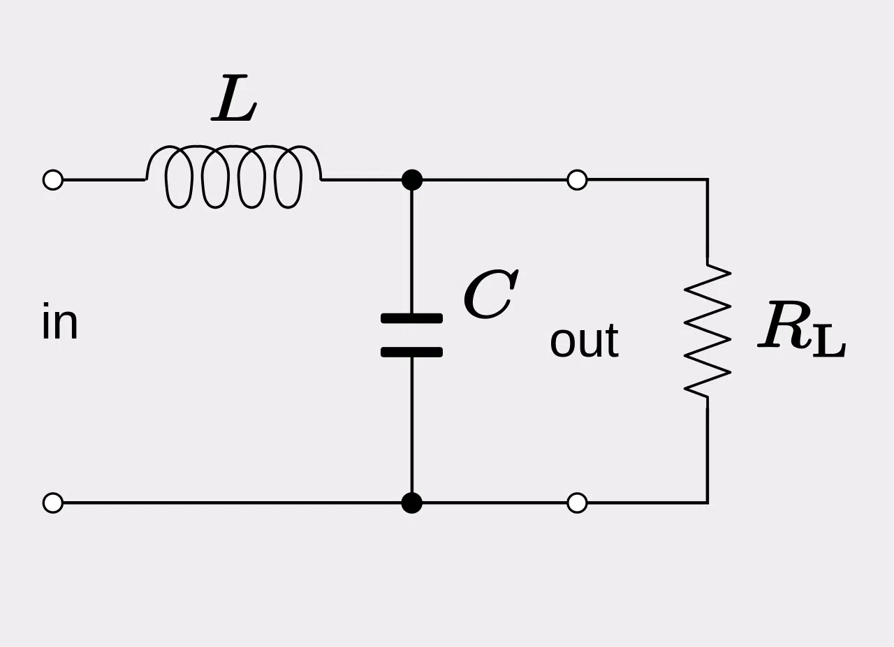
Cut off frequency of the filter will depends on the values of the components chosen for the circuit design. Cut off frequency can be calculated by using the below formula. f C = 1/ The main usage of the low pass filter circuits is to avoid A.C. ripples in the rectifier output. The low pass filter is used in audio amplifier circuits. Applications of passive Low Pass Filters are in audio amplifiers and speaker systems to direct the lower frequency bass signals to the larger bass speakers or to reduce any high frequency noise or "hiss" type distortion. Just want some suggestion design low pass filter circuit for my 40w-4ohms speaker as my subwoofer, thanks. Posted on

Sound engineering: build your own low pass op amp filter with ... Circuit Diagram
If you're interested in electronics or signal processing, you may have heard of a low-pass filter. A low-pass filter is a circuit that allows low-frequency signals to pass through while blocking high-frequency signals. It's commonly used in audio equipment, communications systems, and power supplies to remove unwanted noise or interference.