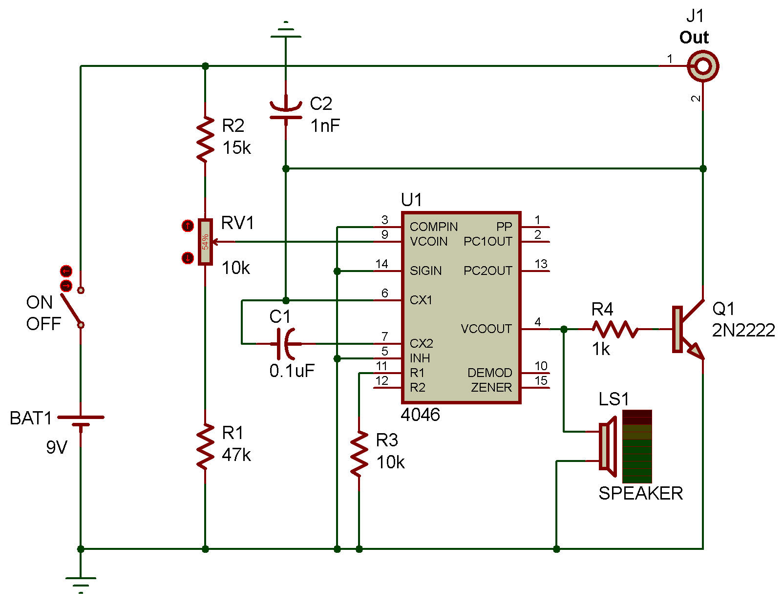
12GHz Voltage Controlled Oscillator With Linear Modulation Circuit Diagram Theory: We are currently modulating voltage with a potentiometer. If the frequency is altered based on this change in DC voltage, a change in DC voltage from a different source should also modulate the frequency. Practice: You want the voltage from your sensing circuit to match the voltage range you identified by sweeping voltages above. If Visualize a gadget that makes sounds like a whistle, but you can control how high or low the pitch is with a knob.. That is kind of what a voltage controlled oscillator VCO circuit does.. It is an electronic device that creates a continuous signal often a square wave and uses a voltage to change how fast that signal vibrates, making the sound higher or lower.

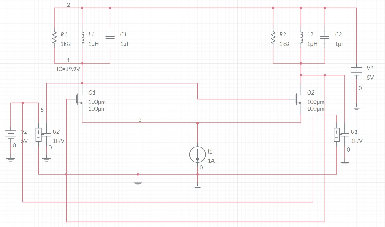
A Voltage Controlled Oscillator is an oscillator which produces oscillating signals (waveforms) with variable frequency. The frequency of this waveform is varied by varying the magnitude of the Input voltage. There are many types of VCO circuits; a very basic one can be built by just utilising a capacitor, As the input voltage (control Oscillator Design. According to the book Oscillator Design and Computer Simulation, a bipolar junction transistor (BJT) can be a good choice for an oscillator in the VHF or UHF range. The book describes an example 300 MHz oscillator using a series inductor and capacitor (LC) circuit (L1 and C6 in the circuit diagram below, 100nH and 3pF A voltage controlled oscillator or VCO is an oscillator circuit which generates a signal with a frequency value varies with the instantaneous input voltage. In this VCO, the Analogread pin A0 is connected to wiper pin of the potentiometer. The terminal T1 of the potentiometer is connected to the 5V pin and the other terminal T2 to the GND.
How to Make a Voltage Circuit Diagram
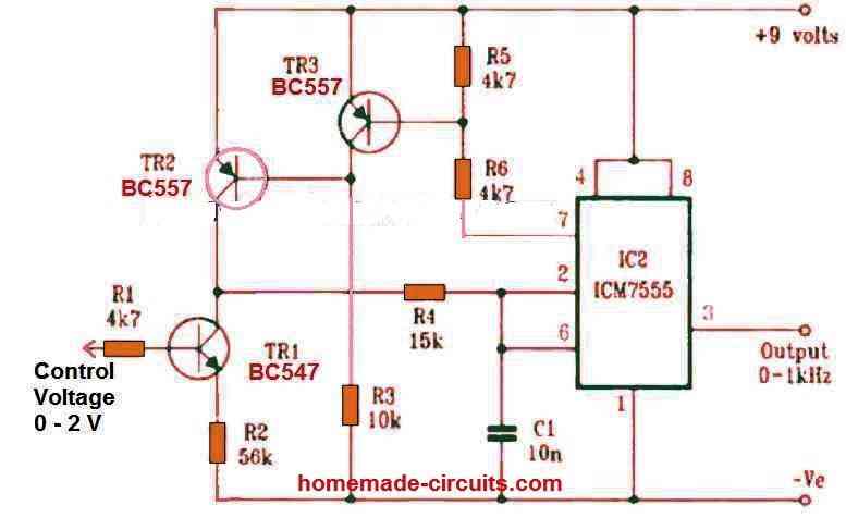
Voltage over the timing capacitor is displayed in the figure, that can vary between + V control and ½ V control. When the control voltage is elevated, the capacitor requires a lengthier time to charge and discharge, the frequency, consequently, diminishes. Therefore, the frequency could be improved by changing the control voltage linearly.

The voltage controlled oscillator (VCO) circuit that we will build using a 555 timer is shown below. The breadboard schematic of the above circuit is shown below. So we will now explain the workings of this circuit. Pin 5 is the control voltage pin. To this pin, we connect a potentiometer to. One end of the potentiometer is connected to
Simple Voltage Controlled Oscillator Circuit Circuit Diagram
Oscillator Design •Introduction -What makes an oscillator? -Buffered output -isolation -Bias circuits -Voltage control -Phase noise. 2 Oscillator Requirements •Power source •Frequency-determining components •Active device to provide gain •Positive feedback •Simple, Stable, Popular •Uses resistor and capacitor