GSM device remote control Circuit Diagram
GSM device remote control Circuit Diagram The Terminal Adapter establishes communication between the Terminal Equipment
Question Everything, Understand More Quincy Nirving.
Simple DC Motor Speed Control Circuit Circuit Diagram Another Simple PWM DC Motor Controller Circuit
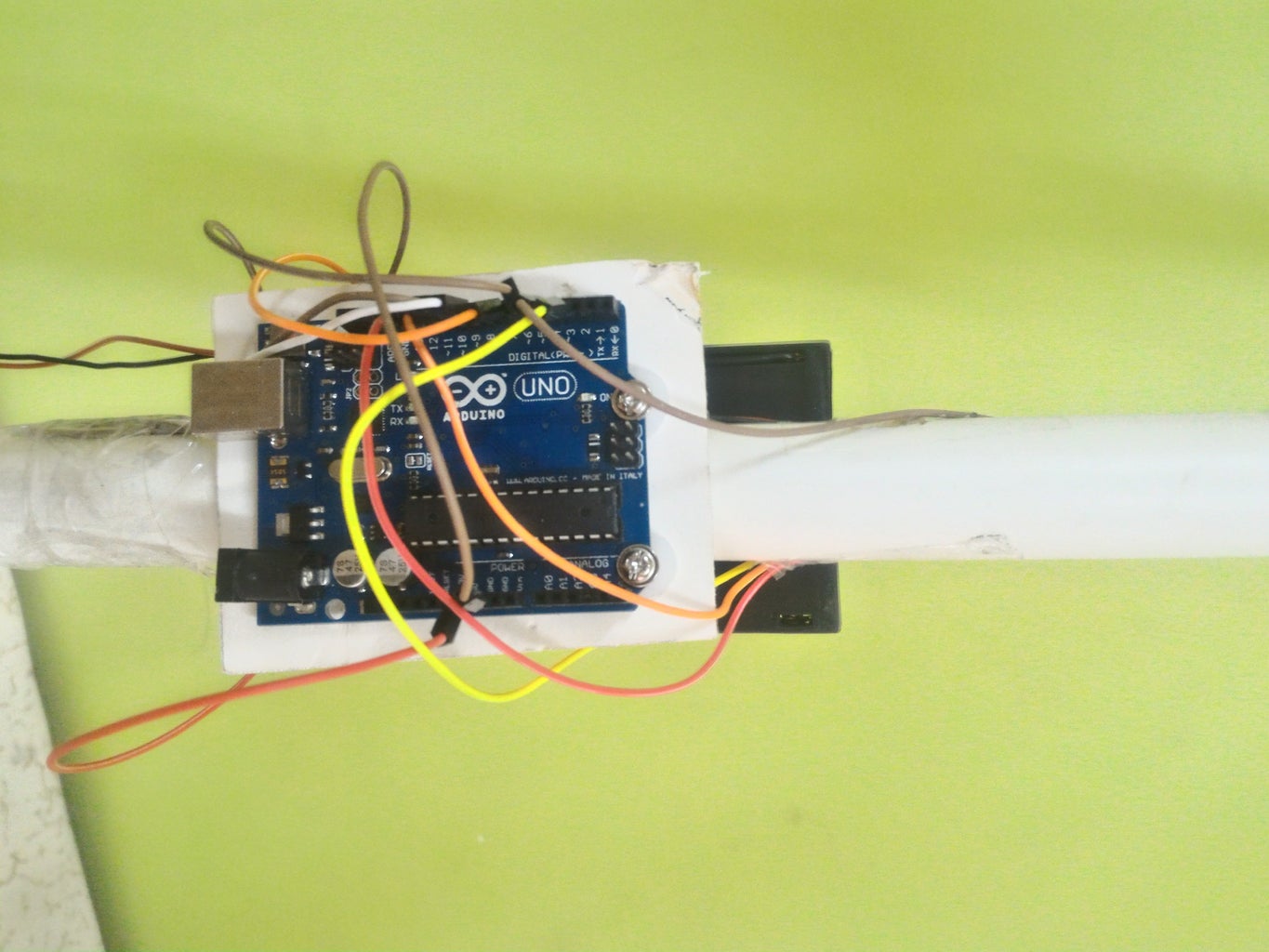
Experiment Circuit Diagram There are a couple more finishing touches to complete the fan. 1.
Microphone design tutorial part 2 Circuit Diagram Now we're going to build the simplest microphone
Building Your Own AI Companion The GPT Home Assistant on Raspberry Pi Circuit Diagram Recommended
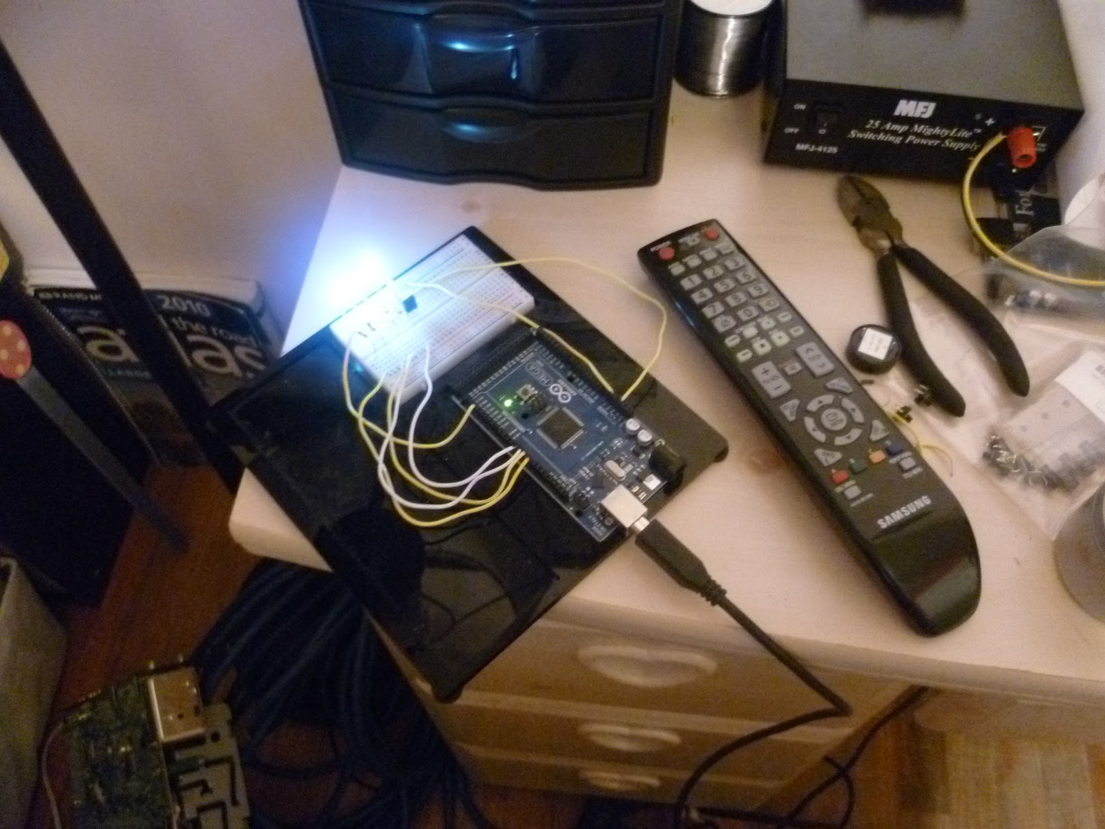
Arduino IR Remote Control Circuit Diagram Now I'll show you a simple demonstration of how
RFID Based Attendance System Using Arduino RTC LCD Display Circuit Diagram Learn how to create
How to Make an Arduino Door Alarm Using an Ultrasonic Sensor Circuit Diagram The project
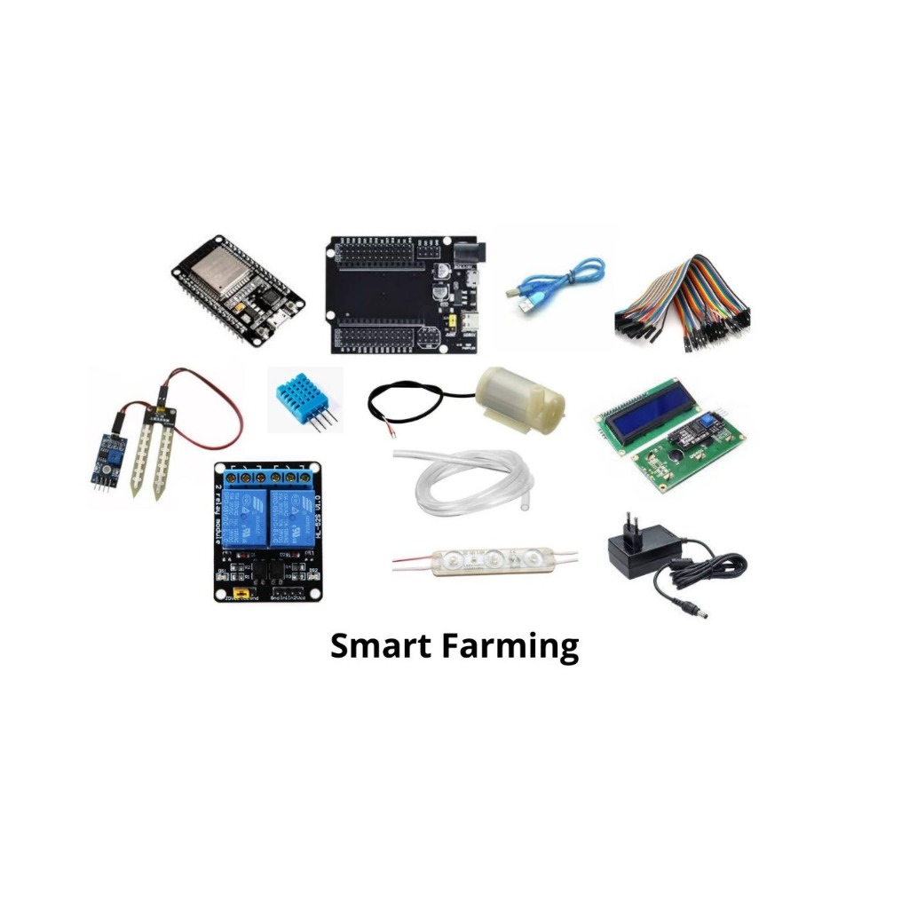
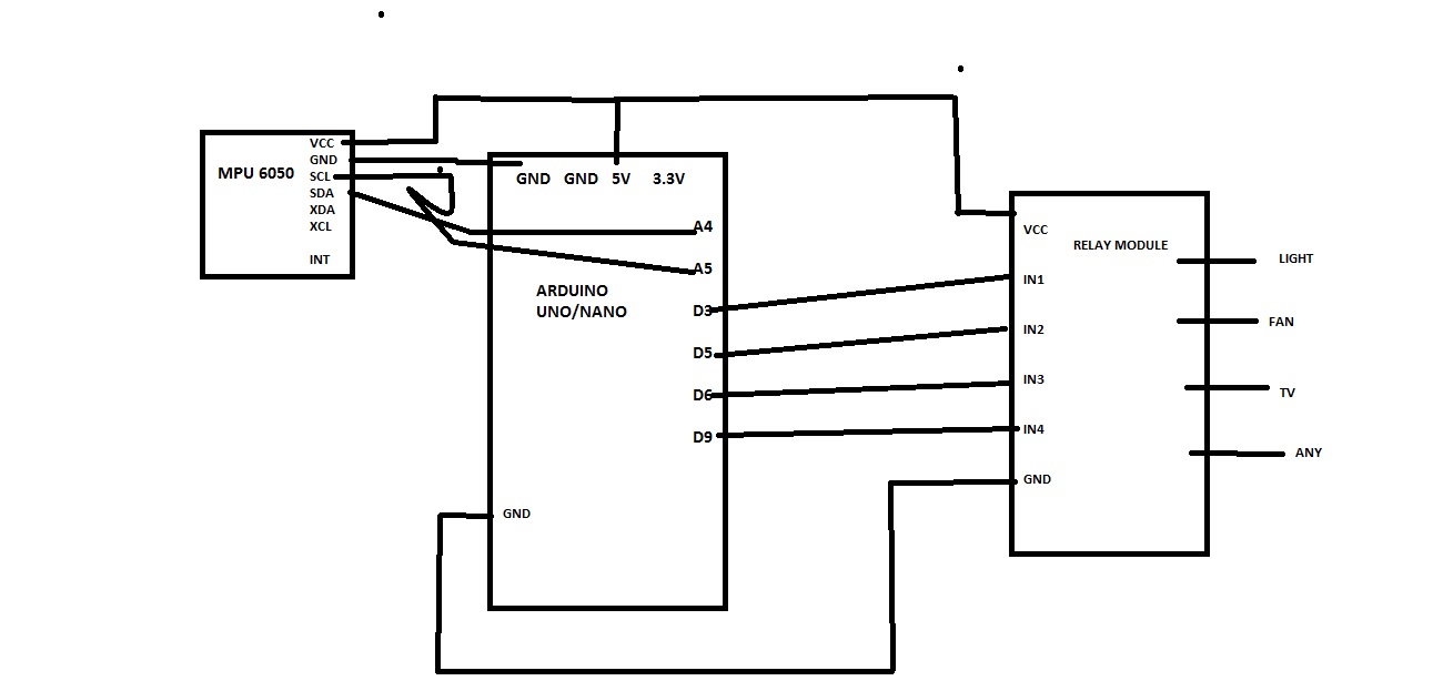
Home automation how to add relays to arduino Artofit Circuit Diagram Connecting LDR to Arduino
Smart Blind Stick 6 Steps Circuit Diagram Smart Blind Stick Using Arduino With Ultrasonic Sensor
Handwritten Character Recognition Circuit Diagram As an AI system, I strive to offer the most
LED CUBE Circuit Diagram LED Cube Display: In this project, you will build an 8x8x8
Vending machine Arduino Machine Circuit Diagram To develop a better system, an " Arduino Based
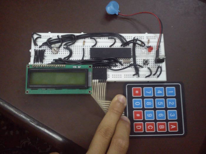
Keypad Locking System with User Defined Password Circuit Diagram 555 Timer electronic Door lock; RFID
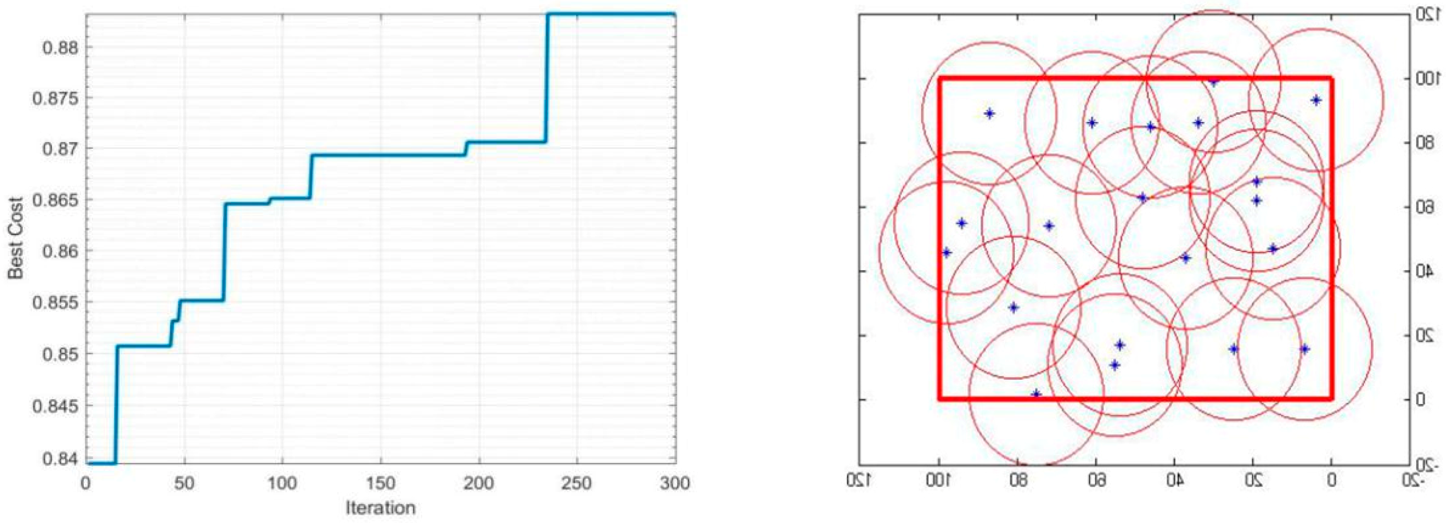
A Method to Construct an Indoor Air Circuit Diagram A Noise Pollution Monitoring System is
Active Low Pass Filter Graph Circuit Diagram In general, the first-order low-pass filter finds wide
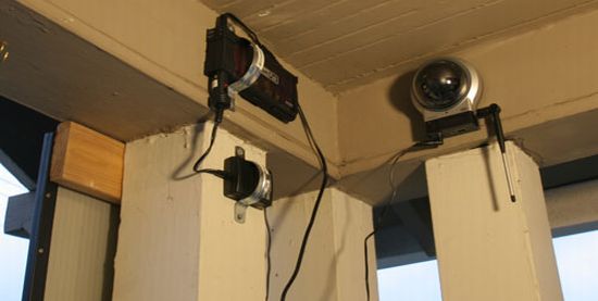
How to make a solar powered wireless security camera Circuit Diagram Introduction: Why opt for
A Simple Light Detector Analog Devices Wiki Circuit Diagram A phototransistor is an incredibly useful
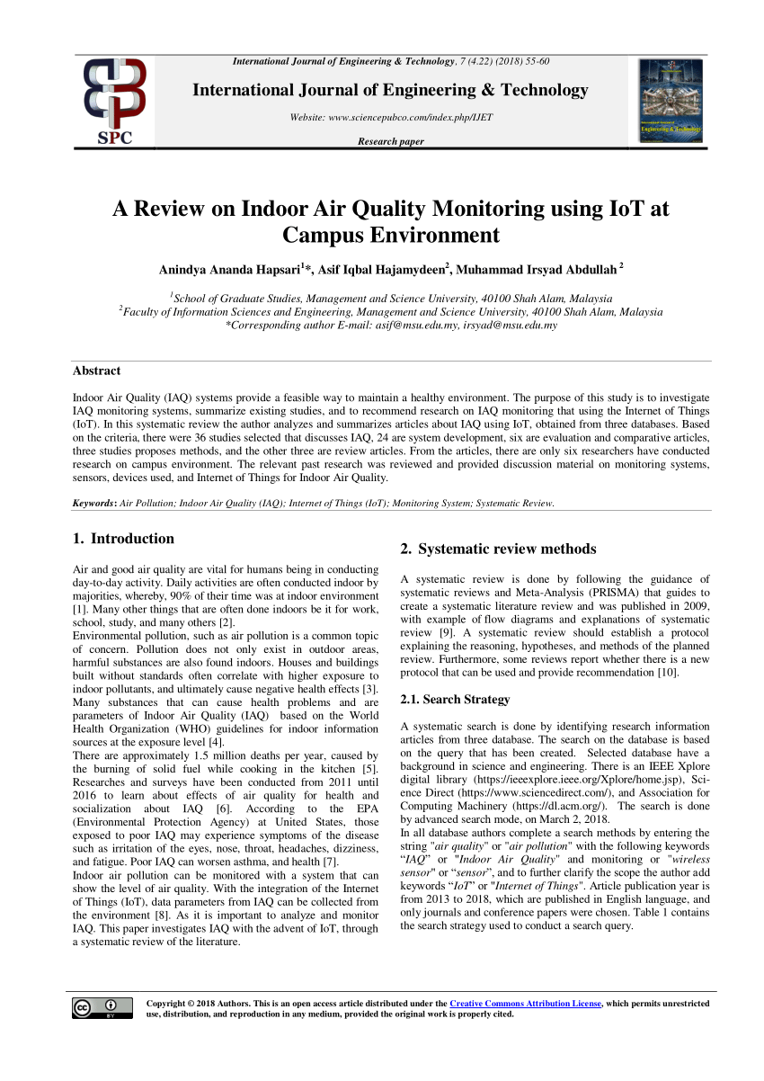
PDF A Review on Indoor Air Quality Monitoring using IoT at Campus Circuit Diagram Difference
7 tips for high Circuit Diagram PCB routing is a critical aspect of electronic design
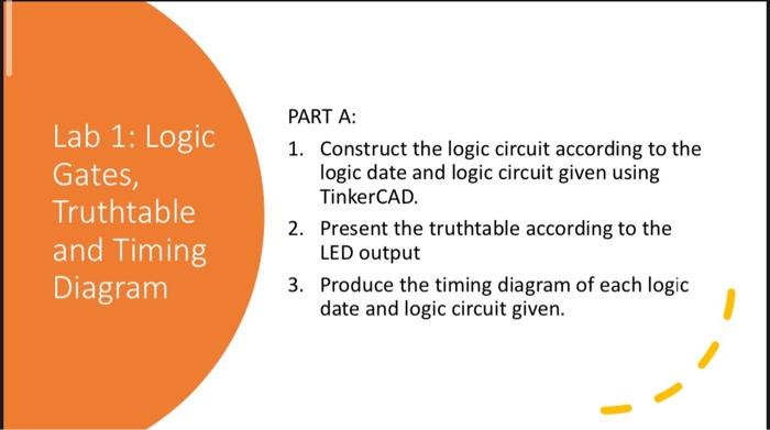
Solved 1 Construct the logic circuit according to the logic Circuit Diagram The basic adding