PIR Motion Sensor Digital Input 7 Steps Circuit Diagram
PIR Motion Sensor Digital Input 7 Steps Circuit Diagram The PIR sensor is adjustable by
Explore Everything, Discover More Quincy Nirving.
WiFi Home Automation Using ESP 8266 Circuit Diagram In this tutorial, we will learn how
Scheme of the setup used as a temperature monitoring system Circuit Diagram Refrigerator Temperature Monitoring
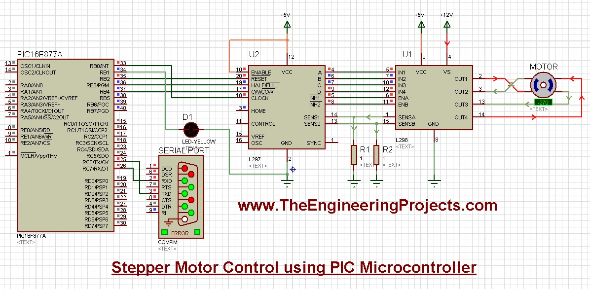
Lecture 3 in microprocessor and interfacing part2 Circuit Diagram Circuit Diagram and Explanation. Circuit diagram
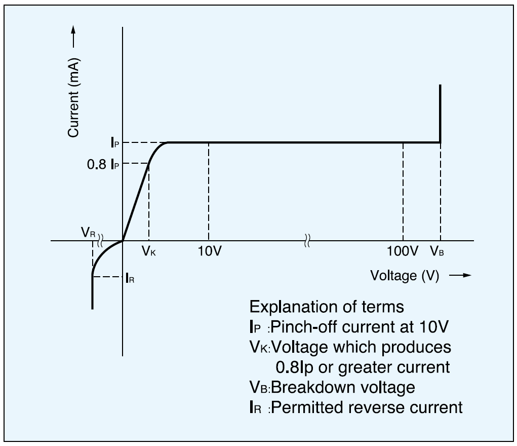
Current regulative diodes Circuit Diagram Figure 1 shows a simple current limiting circuit. As the
Homemade Adjustable Power Supply Voltage And Current Control Circuit Diagram V in is the input
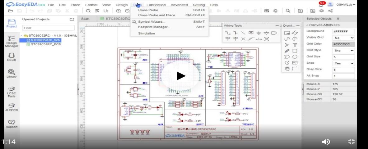
Best Free Circuit Simulator The Best 13 Simulator software Circuit Diagram Learn about free and
Smart City and Smart Home Implementation Using IoT Circuit Diagram Its compact form factor and
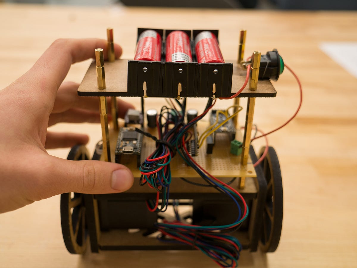
SelfBalancing Robot Final project for ENGR2410 Signals and Circuit Diagram 5)The IMU mpu6050 is not
Circuit Diagram Of Transistor As A Switch A transistor switch is a circuit in which
Capacitors Application VoltageRecommended Capacitors Circuit Diagram Connecting a 1 µF capacitor from VIN to GND
How To Make Motion Sensor Light Homemade Circuit Diagram Took me a little while to
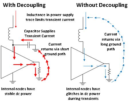
The decoupling capacitoris it really necessary Circuit Diagram The physical placement is of the utmost
Rapid PCB Prototyping Service UK Circuit Diagram Protolabs is the world's fastest source for custom
Free Printable Resistor Color Code Charts PDF Excel Circuit Diagram Learn how to identify and
Building a Super Simple AM Radio Transmitter Circuit Circuit Diagram The tuner typically consists of
Fi IoT Innovation With Ultra Circuit Diagram Introduction: Easy IOT - Low Power Wireless Temperature
The overall smart baby monitoring system a baby sleeping b smart Circuit Diagram To address
Automated Toll Collection System using RFID Arduino Circuit Diagram Materials required for Automated toll collection
DDS Function Generator Function Generator DIY KIT Pulsed Sine Circuit Diagram This is a simple
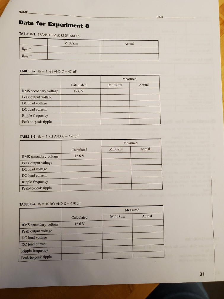
Experiment The Capacitor Input Filter By connecting Circuit Diagram As proposed, to design a high-pass